Copyright © Tony Jeffree, 13 December 2000. All rights reserved.
While constructing the 3/4 second pendulum clock as described in John Wilding's excellent series of constructional articles, I have made some modifications that have made the drive system rather easier to set up correctly, and that ensure correct operation under a variety of operating conditions. As other constructors may find these modifications useful, I have documented the changes, and the rationale for them, in this short article.
Correct operation of the movement as described in the series is critically dependent upon two conditions:
These conditions for correct operation are needed because it is quite possible for the total travel of the Operating Lever (Figure 220 of Part XIV) to be very close to, or even exceed, the span of two teeth of the clock's count wheel. The length of travel of the Operating Lever is directly related to the pendulum's arc of swing. In correspondence with John Wilding regarding this point, he suggests that the clock should be set up such that the arc of swing of the pendulum, measured at the centre of its armature, does not exceed 3.5 inches; there is no advantage to a greater arc of swing, as this will result in higher current consumption from the batteries and an increase in circular error, the latter resulting in poorer timekeeping. In reality, I believe that the circular error issue is largely irrelevant for a clock of this type, given that the operation of the Hipp mechanism acts to keep the arc of swing within close limits; however, there is no particular advantage to be gained by having a large arc of swing.
My calculations would indicate that a 3.5" arc of swing gives an operating lever movement of 0.165"; this is very close indeed to the span of two teeth of the count wheel, which I calculate to be 0.1669", based on the inner diameter of the teeth (1.0625").
If conditions 1 and 2 are met, the clock will operate correctly even if the movement of the Operating Pawl approaches or even very slightly exceeds the span of two teeth, as was the case with my clock in its original configuration. So, if both of the above conditions hold, there would appear to be no problem at all; the clock works just fine.
However, if there is sufficient friction in the drive train, excessive movement of the Operating Lever can result in the Operating Pawl gathering two teeth per swing of the pendulum instead of one. On my clock, which was initially set up with an arc of swing of approximately 3.5", it was very easy to demonstrate that artificially induced friction in the train (a finger lightly applied to the edge of the count wheel) rendered it impossible to make the clock run properly regardless of the adjustment of the Operating Lever.
It seemed to me that it would be easy to modify the design so that correct operation is only dependent on the correct adjustment of the Operating Lever. Consequently, the clock would run correctly even if the rest of the movement was not sufficiently free running or if the pendulum arc of swing was too great. There are a number of reasons why ensuring that the movement would work correctly under such less-than-ideal conditions seemed to be a good idea:
The design as shown in the series calls for a fixed length of 1" for the Operating Lever, and therefore a fixed movement of the Operating Pawl for a given arc of swing. Hence, there is no possibility of adjusting the operation of the movement to compensate for any deviation in the actual arc of swing of the pendulum from the arc assumed when this choice of length was made. Clearly, if the effective length (the distance between the axis of the Crutch Arbor and the Operating Pawl pivot) could be adjusted, this would directly affect the movement of the Operating Pawl.
The design upon which this series of articles was based is one that originally appeared in Model Engineer in the 1950's, and was re-printed, essentially unchanged, in the somewhat short-lived publication, "The Clockmaker", some 40 years later. As I happened to have a full set of "The Clockmaker" to hand, I took a look to see how C.R. Jones's original design had been described.
Unlike its modern sibling, C.R. Jones's design allows the length of the Operating Lever to be adjusted, but not its angle relative to the crutch arbor. Consequently, it allows the distance of movement of the Operating Lever to be adjusted, by shortening or lengthening its effective length. This adjustment is provided by using a rather heavier, square section crutch arbor, with a dovetail slot cut in it; the Operating Lever is shaped to a matching dovetail cross section, and a simple clamping plate allows the lever to be fixed in the appropriate position. It is straightforward with this arrangement to make sure that the Operating Pawl movement is less than 2 teeth. However, it is rather more difficult to set up the ideal position for the Operating Lever with the pendulum at rest (condition 1 for correct operation, stated above), although this rest position will inevitably change slightly as the length of the Operating Lever changes. The total length of C.R. Jones's Operating Lever is 1" from the Operating Pawl pivot hole to the end of the dovetail. As the crutch arbor is made from 5/32" square section brass bar, it is clear from his drawings that he did not expect the effective length of the Operating Lever to exceed 15/16", and quite possibly expected it to be adjusted to a shorter length. This is borne out by the shape of the clock's front plate, which was shaped to give a good view of the drive mechanism. With my original 1" fixed length Operating Lever made to the new design, the bottom end of the Operating Lever was partially hidden behind the front plate.
From these observations, it was clear that the best approach would be to combine both forms of adjustment, allowing both the effective length and the angle of the Operating Lever to be adjusted. This would allow control over the number of teeth gathered, and also over the rest position of the Operating Lever. It didn't take long to work up a suitable double clamp and a modified Operating Lever that could provide both adjustments.
The fully adjustable version of the Operating Lever has two components, as shown in Figure 1. The first is the lever itself; the bottom end of this looks very like the version shown in Figure 220 of Part XIV, but the rest of the lever is a plain shank of 3/32" diameter, giving 1" from pivot to end. I made this by turning down the original Operating Lever that I had made to the Figure 220 dimensions. This left me with an arm slightly under the length shown in Figure 1, but it works just fine. An alternative construction would be to use a shorter piece of square section brass for the pivot end, drill it to take a piece of 3/32" diameter silver steel for the shaft, and Locktite it in place.
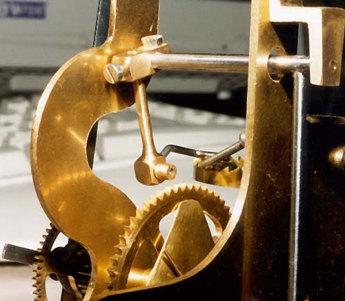
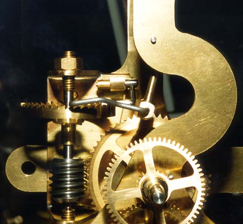
The clamp is formed from a 1/2" length of 3/16" square brass bar. One end carries a split clamp to attach the arm to the crutch arbor; the other end has a 3/32" hole at right angles to the crutch arbor clamp, with an axial hole drilled and tapped to take a setscrew for the Operating Lever length adjustment. A flat is filed on the Operating Lever to take the setscrew. Assembly is pretty obvious; the clamp is fitted to the crutch arbor so that when the crutch is hanging vertically, the clamp extends to the right (viewed from the front of the clock), with the split clamp's screw head accessible from above. The Operating Lever, with Operating Pawl fitted as before, is then inserted into the 3/32" hole, and held in position with its setscrew. The assembled lever and clamp can be seen in the next two photos, which show my clock movement in an unfinished but running state. The second photo shows, with the adjustment to the Operating Lever, that the whole of the lever is now visible in the front plate cutout.
It is worth a note in passing regarding the geometry of the Backstop Arm and Operating Pawl. Figure 211 of Part XIII shows the locking face of the Backstop Arm as perpendicular to the axis of the arm; i.e., if you laid the Backstop Arm flat on the bench, the flat locking face would be in a vertical plane. This diagram is slightly misleading; the angle of this locking face really needs some fine adjustment for correct operation.
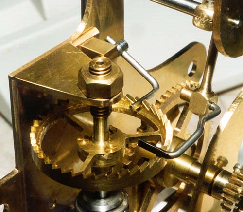
With the count wheel and backstop in their operating positions, and with the backstop locked against the vertical face of one of the count wheel teeth, making the locking face as shown in the original diagram will mean that the face is tilted significantly from the vertical. This is due to the fact that the Operating Lever pivot is mounted somewhat above the plane of the count wheel, so the Operating Lever is angled downwards in operation. The locking face must be formed such that, in the locked position (the arm having just dropped off one of the teeth of the count wheel), the face is vertical, as can be seen in the next photo. Ideally, the shape of this component would be further improved by forming a second flat on the underside, at an angle to match the ratchet cutter used. These modifications help to make the ratchet action operate cleanly, and more importantly, they will ensure that a full tooth width of movement is required in order to drop the backstop arm off the tip of its current tooth and into the next tooth space.
The same comments also apply to the flat face of the Operating Pawl; this should be adjusted such that its face is vertical when the pawl is acting against the vertical face of a tooth of the count wheel. It is not possible to finally adjust this component until the effective length of the Operating Lever has been fixed, as described below.
If the operating faces of the Operating Pawl and the Backstop Arm are not adjusted correctly, then it is possible for the mechanism to gather two teeth even if the movement of the Operating Lever is less than the width of two teeth. It is easy to see why this would happen, by reference to Figure 2 (the angle of the Backstop Arm is shown slightly exaggerated in order to make the effect more apparent). If the locking face of the Backstop Arm is angled such that it only contacts the tooth at its tip, then the lower edge of the face is already part of the way up the ramp towards the next tooth tip (see Figure 2a), hence, somewhat less than a tooth's width of movement will gather the first tooth. Similarly, if a second flat is not formed on the underside, then the point of contact between the ramp and the lower surface of the Backstop Arm will not be the lower edge of the locking face (see Figure 2b). This may result in the arm dropping off the tooth slightly early, although this is a much less significant factor than the angle of the face. The ideal cross-section for the business end of this component can be seen in Figure 2c.
The arc of swing of the pendulum changes a small amount between the maximum arc just after an impulse from the electromagnet and the minimum arc on the swing just before impulse. The effective length of the Operating Lever should be adjusted so that the minimum arc of swing of the pendulum gives around 1.5 teeth of Operating Lever movement, and the maximum arc of swing still gives less than 2 teeth. This can be checked visually by applying a small amount of resistance to the drive train, so that the return stroke does not cause the count wheel to recoil, and observing the action of the Operating Pawl in the cycle just before the contacts are tripped.
The angle of the Operating Lever relative to the crutch arbor can then be adjusted to match condition 1 above; i.e., with the count wheel rotated against the backstop's locking face, the face of the Operating Pawl is mid-way between two teeth; this condition can be seen in the second photo. On my clock, setting the two adjustments in this way gives an effective length for the Operating Lever (measured between the crutch arbor pivot and the operating pawl pivot) of approximately 13/16", as opposed to the original 1".
Setting the Operating Lever as described should achieve the desired objective of ensuring correct drive operation under all conditions, whether the movement is free-running or not. Applying a finger lightly to the edge of the count wheel should demonstrate that this is so; it will be observed that the mechanism will operate correctly in the face of quite considerable friction in the drive train. This is clearly an undesirable condition for long-term running, from the point of view of the clock's timekeeping, wear on its components, and the longevity of its batteries; the ideal here is for the train to be free running, as indicated in John Wilding's series. However, it demonstrates that, properly adjusted and with these modifications applied, the clock should be capable of running correctly despite the effects of dust and thickened clock oil, or despite the limited skills of a first-time clockmaker.
Improvements to the 3/4 second Pendulum Clock
© Tony Jeffree 2000
All Rights Reserved
Email me at this address...
website ({at}) jeffree.co.uk
Return to Model Engineering Activities page...