Copyright © Tony Jeffree, 4th August 1999. All rights reserved.
The Peatol micro lathe (Ref 1), manufactured in the USA as the Taig lathe (Ref 2), provides a very cost-effective means of entering the world of metal turning, for clock making or other light model engineering uses. One of its limitations, as the uses to which it is put become more sophisticated, is that it has no leadscrew; hence, it cannot be configured for fine feeds, or change wheels fitted to allow it to be used for cutting threads.
Other lathes of a similar size have leadscrew and screw cutting ability; notable among these is the Sherline (Ref 3), which also allows fine feed to be obtained via a supplementary motor attached to the leadscrew. An accessory kit is available for the Sherline that adds the screwcutting capability; this consists of a suitable selection of change wheels, sector arms, and a handwheel which allows the lathe spindle to be driven by hand during the screwcutting process rather than by the lathe motor.
The thread cutting capability of the Sherline kit is fairly comprehensive. The Imperial version of the lathe has a 20 TPI leadscrew, and the kit allows most useful Imperial threads to be cut. The kit includes a 127T wheel to allow Metric threads to be cut as well. This introduces one of the curiosities of the Sherline change wheel set. The majority of the wheels are 24DP; however, there are a small number of 60DP wheels, two 100t wheels, one 127T and one 50T. These are used exclusively as the first driver and driven wheels in the Sherline set-up, using the smaller tooth pitch in order to include the magic 127T wheel for metric conversion without the wheel size being ridiculously large. The 24DP wheels are bored 3/8"; the 60DP wheels are bored 9/16".
Reading through the Sherline product literature, it struck me that their screwcutting kit might be a useful starting point for building similar capability into a Taig lathe. I went ahead and bought the kit, to see if I could then think through a suitable design using some or all of its components. Clearly, it would be necessary to improve on the "hand cranked" approach of the Sherline kit, as this would be desirable for providing a sensible fine feed. Including a tumbler reverse would also be an essential part of the design, as this would allow forward/reverse/neutral drive to the leadscrew. Similarly, incorporating a dog clutch to allow the leadscrew to be disengaged from the gear train would be essential; otherwise, fine feeding the carriage by hand would become a little strenuous. This will be apparent to anyone who has tried to move the carriage by turning the leadscrew handwheel on a lathe with no clutch, with a fine feed gear train engaged. Also, I considered the ability to disengage the saddle from the leadscrew (not possible on the Sherline) to be highly desirable, thus allowing the Taig's existing rack & pinion to be used for fast saddle traverse. So these features formed the initial "shopping list" for the project, along with the very basic requirement to be able to configure the lathe for a sensible fine feed, which on a lathe of this size means a very small number of thou of saddle feed per spindle revolution.
The first problem, that of obtaining a sensible drive to the gear train from the lathe spindle, took considerable thought, particularly given the intent of including a tumbler reverse. The lathe uses a stepped pulley as its primary drive from a similar stepped pulley on the motor shaft. There is little space between the pulley and the headstock, and the pulley overhangs beyond the end of the lathe spindle, so direct attachment of a gear wheel to the spindle itself did not look like a good option. Besides, I already had that particular space earmarked for permanent attachment of a dividing plate at a later date.
I considered making an adapter that could be inserted in the bore of the pulley, held in place by a drawbar through the spindle from the spindle nose. While this would be workable, it would have the obvious disadvantage that it would remove any possibility of using the spindle bore, for collets and so on, so I abandoned this idea as unsuitable. A close examination of the pulley itself revealed that there is just about enough metal at the tail end of the pulley (the smallest diameter end) to make it possible to attach a small gear wheel directly to the body of the pulley using longitudinal screws through the gear wheel, threaded into the body of the pulley itself.
The Sherline gears are aluminium, and around 3/16" thick; I figured that while these might be OK for light, occasional use, cutting threads for example, I would need to use something more robust as the basis for the tumbler reverse arrangement and for the gears used in the fine feed configuration. All of the additional gears that I used are chosen from the 24DP range manufactured by HPC Gears (Ref 4). These gears are 5/16" thick; bore diameters vary according to the wheel size. The ones I used are steel; however, HPC offer the same range in Delrin, which, while I have not attempted to try them, may well prove to be a viable and cheaper alternative.
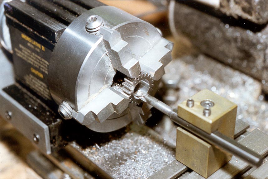
I used a 20T 24DP wheel, HPC part number G-24-20-PG, as the primary drive wheel attached to the spindle. The 20T wheel has a 5/16" bore; this needs to be opened out to the same diameter as the pulley bore, nominally 3/8", in order for the lathe spindle bore not to be obstructed. Opening out the bore retains the ability to fit the standard drill chuck spindle to the headstock, and also to use the full diameter of the spindle bore when turning small diameter stock. I found that it is straightforward to hold these gears in the 4-jaw chuck. By locating the tapered ends of the four jaws in the gaps between opposing pairs of teeth, the wheel can be "automatically" centred to a workable degree of accuracy, assuming that the 4-jaw is itself accurate. Obviously, if inspection with a dial gauge shows that the wheel is not centred, this can be remedied using packing shims as necessary. The bore can then be opened out using a suitable boring bar in my case, a 1/4" boring bar fitted with a Sumitomo titanium carbide insert (Ref 5), which cuts very nicely indeed at these diameters. Photo 1 shows one of the tumbler gears having its bore modified by this means. At first sight, this technique for opening the bore of a gear wheel sounds as if it will damage the gear teeth. However, the wheel is very well located by the tips of the four jaws and therefore only needs to be held with light pressure. A boring bar of this size cannot take heavy cuts; it is therefore apparent that not very much force is applied to the teeth in this machining operation and considerably less than they are designed to handle. My own gears showed no evidence of tooth damage after being modified in this way.
Photo 1: Modifying the bore of a 20T gear
The groove of the smallest drive pulley is approximately .66" diameter at the base of the V; this means that there is a wall thickness of approximately .14" to play with, which is enough thickness to take an 8BA screw. While the wheel is still in the chuck, it is a simple matter to scribe a circle at a diameter of .51" on the face of the wheel for later marking out the drilling positions for the screws. Then mark the four hole positions on this circle, 90 degrees apart. The pulley is then removed from the lathe spindle so that the wheel and pulley can be drilled in a single operation. I found that the wheel and pulley could be held in position during drilling with the aid of a 3/8" steel dowel and the use of Superglue as a temporary adhesive. Drill through the wheel into the end of the pulley using an 8BA tapping drill, then open out the holes in the wheel to 2.2mm to clear the screws. Disassembly of the wheel from the pulley can be achieved by drifting the dowel out and splitting the components apart after drilling; if you avoid cleaning the parts too thoroughly before Superglue application this helps the disassembly process! Cleaning the glue residue off after disassembly completes the drilling operation. The four holes in the pulley are then tapped 8BA, allowing the gear wheel to be fixed in position using suitable 8BA screws. I used cheese-headed screws and found that the heads were just slightly too large to clear the 3/8" bore, so turned them down to a more suitable diameter. Accuracy of assembly of the wheel to the pulley can be ensured by re-application of a 3/8" dowel prior to tightening the screws, ensuring that the bores of the pulley and wheel are concentric. The end result can be seen in Photo 2, which also shows some of the partly machined tumbler support bracket components in position.
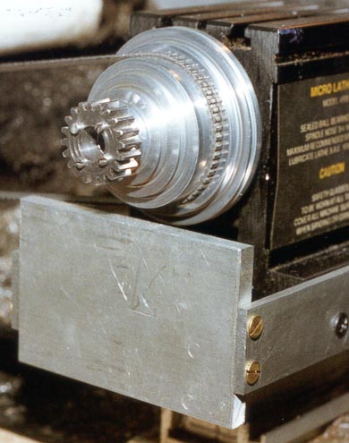
Photo 2: Primary drive wheel attached to the Taig/Peatol drive pulley
At this point, it is possible to refit the pulley to the lathe, which is just as well, as many of the subsequent operations require the lathe to be operational.
Photo 3 shows how the tumbler reverse is assembled onto the lathe. This photo is of an early prototype; the final design uses a much thicker and more robust operating arm, as this one proved to be too flimsy; however, the photo serves to illustrate the fixing arrangement. Construction makes use of the fact that the lathe headstock has longitudinal T-slots running along its base at each side; these provide a temporary fixing method that allows the position of the mounting bracket to be adjusted before final fixing. The mounting bracket is a simple U-shaped frame attached to the headstock; this will hold the tumbler gears in position below the drive gear that is now firmly attached to the lathe's drive pulley.
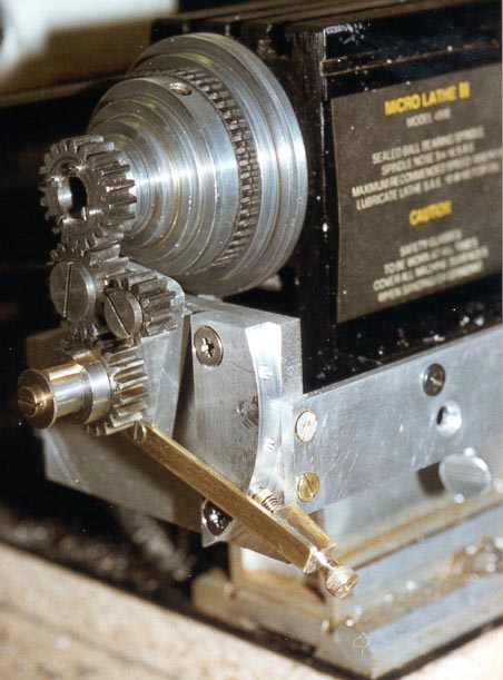
Photo 3: Tumbler reverse assembly
Construction of the tumbler support bracket is straightforward. The two longitudinal arms and the rear plate are shown in Figures 1-3. The front and rear arms are mirror images of each other (Figure 1); both are 4" X 1" X 1/8" aluminium sheet, although the length may be trimmed after final fitting. Drill and countersink the 4BA clearance holes, and the two lower 3/16" holes in each plate; at present, do not drill the upper 3/16" holes. The lower holes are used to take T-bolts and nuts that will slot into the lower T slots on the headstock. 3/16" Whitworth or UNF 10-32 work quite well for this.
The back plate of the support bracket (Figure 2) is made from a 3¼" X 2" rectangle of ¼" aluminium plate, with one corner and some of the top edge sawn off as shown in Figure 1. This material is removed to ensure that there is no chance of the bracket fouling the drive belt or pulley when the unit is finally assembled.
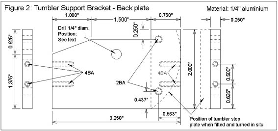
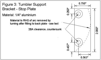
The 3¼" dimension of the back plate should be adjusted to the exact width of the headstock base. Each end of the plate is drilled and tapped 4BA to take the screws to attach the front and rear arms of the bracket. An additional tumbler stop plate (Figure 3), formed from a rectangle 2" X ¾" of ¼" thick aluminium is attached at the right hand side of the back plate (as viewed from the rear of the lathe) by means of two 2BA countersunk screws. This stop plate will eventually be turned to an arc on its outer edge, centred on the tumbler pivot pin, as shown by the dashed arcs in Figures 2 and 3, but not before the remainder of the tumbler has been constructed and test fitted in its final position. Similarly, the ¼" mounting hole for the tumbler pivot pin is not drilled until later.
The two arms can now be assembled with the back plate, the additional rectangle for the stop plate screwed in place, and the whole bracket temporarily fitted to the headstock by means of T-bolts through the lower pairs of 3/16" holes.
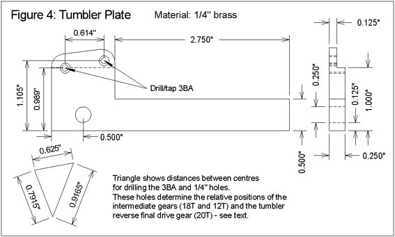
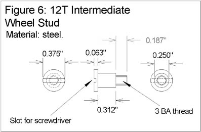
The tumbler assembly is carried on a ¼" thick brass Tumbler Plate, as seen in Figure 4. As the drive wheel attached to the spindle is 20T, the final drive gear from the tumbler reverse is also 20T; the two intermediate wheels are 18T (HPC part number G-24-18-PG) and 12T (HPC part number G-24-12-PG). The difference in diameters between the intermediate wheels is rather greater than is strictly necessary for operation of the tumbler, so a larger wheel might be substituted for the 12T wheel if desired, with suitable dimension changes elsewhere.
The dimensions shown for the relative positions of the gears are based on the Pitch Circle Diameters (PCDs) quoted by HPC for the gears used, and should result in free running of the gears. Clearly, for safety, it is advisable to check that these dimensions will be appropriate for the particular gears used, and adjust if necessary. The calculation is simple; the 0.7915" dimension is half the sum of the PCDs of the 20T and 18T wheels. The 0.625" dimension is half the sum of the PCDs of the 18T and 12T wheels. Finally, the 0.9165" dimension is half the PCD of the 20T wheel, plus the PCD of the 18T wheel, less half the PCD of the 12T wheel.
The two 3BA holes will hold the intermediate wheel studs; the ¼" hole will fit over the pivot stud for the tumbler, which also carries the tumbler output gear and the first driver wheel of the change wheel train.
The plate is cut to size and the three holes drilled and tapped as indicated; then the recess on the rear face is milled or filed out. The recess at the back is necessary in order to avoid the plate fouling the lathe drive pulley. An alternative to using ¼" sheet is to fabricate the plate from two pieces of 1/8" thick sheet, soft soldered together. An advantage of the latter approach is that the hole positions for either of the two 3BA holes can be adjusted more easily if they turn out to be incorrect for the gears to mesh nicely. Remove part of the front face by cutting to 1/8" depth with a hacksaw, and unsoldering it from the rest of the plate. It is then a simple matter to solder in a fresh piece of 1/8" thick brass in its place and re-drill/tap the hole in the correct position. It is advisable to make the arm of the tumbler plate slightly over length to start with, and to adjust it later as described below.
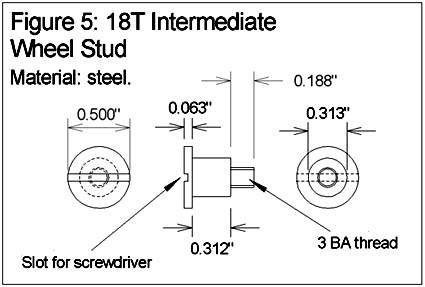
Two steel studs are turned to carry the 18T and 12T wheels. The 18T stud (Figure 5) is turned from ½" diameter steel rod; the 18T wheel has a 5/16" bore, so the stud is turned down to this diameter, leaving sufficient length to be further turned down and threaded 3BA for the last 3/16" of its length. The 5/16" diameter portion is nominally 5/16" long to match the thickness of the 18T wheel; however, this should be left a few thou over length to ensure that the wheel will run free when screwed onto the tumbler plate. The stud is then parted off to leave a screw head about 1/16" thick and a screwdriver slot cut across the head with a hacksaw. The 12T stud (Figure 6) follows the same procedure, this time starting with 3/8" stock and reducing to ¼" for the bore size of the 12T wheel. In both cases, the aim is for a free running fit of the wheel onto the stud.
The two wheels can now be attached to the tumbler plate, with a suitable diameter steel washer under each wheel to prevent direct contact between the wheels and the tumbler plate. Note that the 12T stud is fitted in the hole furthest from the ¼" diameter hole. If all is well, the two wheels should mesh nicely and rotate freely.
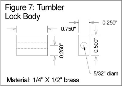
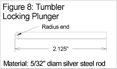
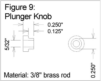
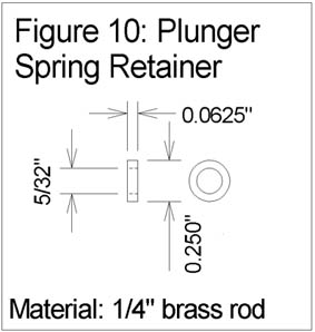
The arm of the tumbler plate carries a locking plunger attached at its far end. This plunger will eventually locate in three holes in the curved edge of the tumbler stop plate, giving locking positions for Forward, Neutral and Reverse for the tumbler. The plunger runs in the Tumbler Lock Body, a block of ¼" x 1/2" brass (Figure 7). The Tumbler Lock Body is soft soldered onto the end of the operating arm, on the side that has the recess at the top edge. It is aligned so that the axial hole points along the centre line of the arm; i.e., on a line to the centre of the ¼" diameter hole in the tumbler plate. However, this is not soldered in position until the radius is cut on the stop plate as described below. Once soldered in place, any excess length of the operating arm is trimmed off flush with the end of the tumbler lock body, and the locking plunger fitted. The locking plunger is a simple length of 5/32" diameter silver steel rod (Figure 8), turned to a radius at one end. A simple brass knob cut from 3/8" diameter rod (Figure 9) is attached at the square end using Superglue, and a thin brass washer cut from 1/4" brass rod (Figure 10) acts as the retainer for the return spring at the radiused end. The knob is glued in place, the radiused end is passed through the axial hole in the lock body, a length of spring from a ballpoint pen serves as a return spring, and the retaining washer is Superglued in place about ½ way along the exposed length of the plunger. Again, the final gluing of the retaining washer is left until the lock body is soldered in place and the arm has been trimmed to length.
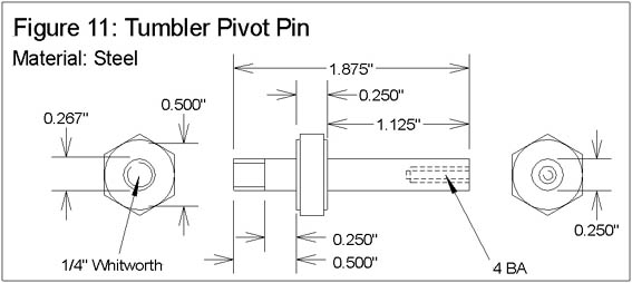
The Tumbler Pivot Pin (Figure 11) is cut from a length of hexagonal steel stock, nominally 0.56" across flats. Face one end and reduce its diameter to ¼" over 1 1/4" of its length. This length will need to be adjusted down later, once the rest of the assembly is complete; for the moment leave it over length. Reduce the diameter to 0.56" for about 1/32" in order to present a circular shoulder. Drill and tap axially 4BA for the screw that will act as the retainer for the final drive boss and the tumbler plate. Reverse the component, face the end, and reduce the diameter to ¼", leaving a shoulder 1/4" wide, again turning off the hexagon for about 1/32". Thread this end ¼ Whitworth and reduce the threaded portion to about ½" long. This acts as the mounting stud for the pivot pin, and will be fitted through the ¼" hole in the support bracket back plate.
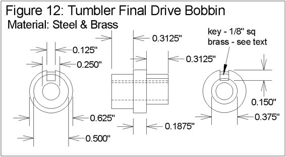
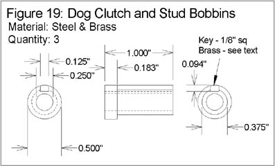
The tumbler final drive gear (a 20T gear see above) is carried on a bobbin that also carries the first driver gear wheel of the changewheel geartrain. The bobbin is shown in Figure 12. The Sherline 24DP gears have a 1/8" wide keyway cut into the bore; the bobbin has an integral key to match, hence allowing any of the Sherline 24DP gears to be used, unmodified, as the first gear in the changewheel geartrain. The 60DP gears can also be used once modified to reduce the bore to 3/8", as described later in this article. Construction of the bobbin starts by increasing the bore size of a second 20T gear (HPC part number G-24-20-PG) to ½" diameter, using the technique already described, illustrated in Photo 1. Then chuck a suitable length of 5/8" round steel bar; turn down the last 5/16" to be a press fit into the bore of the 20T wheel. Leave a 3/16" shoulder at full diameter, then turn down a further 5/16" length to 3/8" diameter, bore the piece ¼" diameter and part off to length. The channel for the keyway is milled (or very carefully filed) to 1/8" wide along the entire length of the part, taking care not to cut too deeply into the 3/8" diameter portion. Milling is definitely to be preferred the Peatol/Taig milling slide is invaluable for this kind of operation. A length of 1/8" square brass bar is then cut and soft soldered into the milled channel. Return the part to the lathe to clean up the ends of the key, and also to trim the excess that will protrude from the ½" diameter end. Press the 20T gear into place, securing with a suitable adhesive if necessary. The remainder of the brass key may need some final adjustment in order to fit the keyways in the Sherline gears. Leaving the keyed portion of the bobbin at 5/16" length will allow either Sherline gears or further HPC 24DP gears to be used in the changewheel train.
Now that all the components for the tumbler assembly have been made, the final machining and setting up of the support bracket and the tumbler can be completed. First, machine the pivot pin to its final length. Place the tumbler plate over the pivot, followed by a suitable washer (of the same thickness as those used under the idler wheels), and the completed final drive bobbin. The pivot pin should just slightly protrude from the bobbin; i.e., when a 4BA screw and washer is screwed into the end, it will retain the components in place while allowing the bobbin to run freely.
With the bobbin and plate assembled on the pin, check that the lower three gears of the tumbler now mesh correctly. Assuming all is well, mark the position of the hole in the back plate of the support bracket that will take the pivot pin. This should be vertically below the centre of the lathe spindle, and should be positioned to allow the tumbler's idler wheels to mesh correctly with the pulley's drive gear. The position of the support bracket should be adjusted on its T bolts to ensure that all the gear wheels end up in the same plane. Drill the hole in the back plate ¼" diameter, fit the pivot pin in the hole with a suitable nut and washer, and check that the gears still mesh correctly in both forward and reverse positions. If necessary, the hole in the back plate can be enlarged slightly to get proper alignment.
Remove the back plate from the support bracket, screw the stop plate in place, and mount the assembly in the 4-jaw chuck to turn the arc on the stop plate. It will be necessary to reverse two of the jaws to achieve this feat; the plate is centred so that the pivot pin is on the centre line. While the back plate is removed, spot through the upper pairs of holes in the side arms of the bracket, drill and tap into the headstock extrusions for suitable 3/16" bolts to act as the permanent fixing method for the bracket. The temporary T bolts can then be removed, thus allowing the saddle stop to be used once more.
Re-assemble the back plate and pivot pin in position, checking that alignment is still good. Re-fit the operating arm to the tumbler plate; assemble it onto the pivot, followed by the washer and bobbin. Retain the components in place with a 4BA screw and washer (if you are feeling very energetic, make up some 4BA screws with suitably large heads as an alternative that avoids the perennial vanishing washer problem!). Temporarily clamp the locking assembly in position on the tumbler plate, adjusting the position of the lock body so that, when the locking pin is fully retracted, it just clears the edge of the stop plate. Remove the tumbler plate from the assembly, soft solder the lock body in place, finish the arm to length, re-fit the locking pin, spring and retainer, and fit the complete tumbler plate and locking assembly back onto the pivot. Mark on the stop plate the position of the tumbler locking pin when the tumbler is in the forward, neutral (disengaged) and reverse positions, and drill a centre hole at each position with a centre bit in preparation for drilling the locating holes for the locking pin. Drill locating holes at each of the three positions. These are ideally 5/32" diameter, and deep enough to allow the locking pin to extend fully into the locating hole. If your drilling is accurate (i.e., exactly on a radius centred on the tumbler pivot pin), then 5/32 may work fine; for lesser mortals, enlarging these holes to 3/16" or 7/32" may be necessary for easy operation of the tumbler lock.
At this point, you should have an operational tumbler reverse drive in position, capable of taking gearwheels of up to 5/16" in thickness, without disturbing the original functions of the lathe. One minor detail here is that the steel rod used as the saddle stop will now be too long for operations close to the chuck, as it fouls the support bracket's back plate. This can be remedied by cutting a second, shorter, saddle stop bar to be used under these circumstances, retaining the original one for working further from the chuck.
Photo 4 shows the general positioning of the dog clutch body; the clutch is supported on a simple aluminium angle bracket (Figure 20) that is bolted into the aluminium foot of the lathe. The clutch mounting bracket also provides a convenient retaining cover for the operating components of the clutch. The brass operating lever can be seen protruding from the clutch body, in the disengaged position.
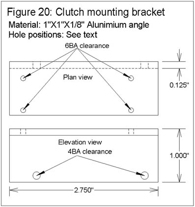
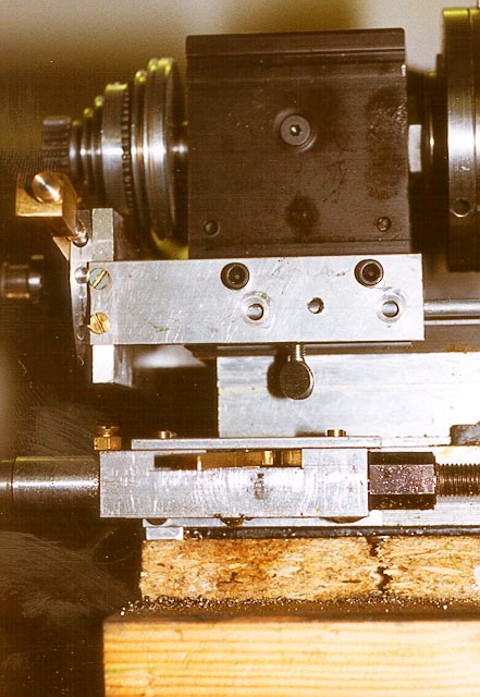
Photo 4: Dog clutch positioning
The clutch operation is very simple indeed. The shaft into the clutch (Figure 16) has a groove cut in it into which a 2BA bolt (seen on top of the clutch body) locates, thus ensuring that the shaft stays in its correct lateral position but can rotate freely. The visible end of the shaft is a bobbin similar to the one used for the output gear of the tumbler assembly (Figure 19); the main difference is its length and the fact that in this case it is an integral part of the shaft. A suitable gear wheel can be placed on the bobbin, along with spacers to line it up with its driver wheel; another 4BA screw and washer retain these in position.
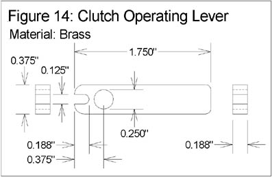
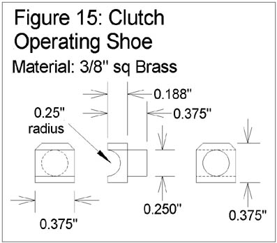
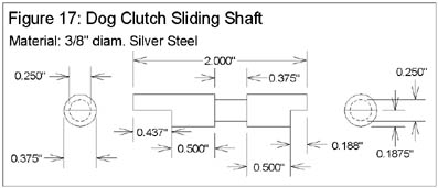
The opposite end of the input shaft (the end within the clutch body) is filed to a D section over the last ½" of its length. This D section constantly engages a short sliding shaft (Figure 17), which has a similar ½" D section at its near end, and a shorter, 3/8" long D section at the other. A groove in the centre of this shaft carries the clutch operating shoe (Figure 15), which in turn is pivoted in a hole in the clutch operating lever (Figure 14). Hence, as the operating lever moves to the left or right, so does the sliding shaft. The output shaft (Figure 18) from the clutch has a 3/8" long D section at its near end. The lengths of the components have been chosen such that, regardless of the position of the operating lever, the sliding shaft's D section always engages the D section of the input shaft. However, the D section of the output shaft is engaged only when the lever (and the sliding shaft) is moved to the right. This is crude but effective, and above all, fairly simple to make.
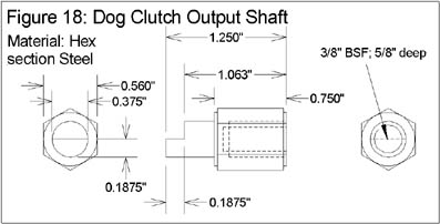
The output shaft from the clutch is threaded 3/8" BSF (20 TPI) to take a suitable length of BSF studding for the leadscrew (Ref 6). Clearly, this means that the "sense" of operation is the reverse of most leadscrews (conventionally, leadscrews use a left-hand thread); if this is a problem, it may be possible to obtain left hand BSF studding (or have it cut) and left handed taps. You will have detected by now that this did not worry me sufficiently to do anything about it!
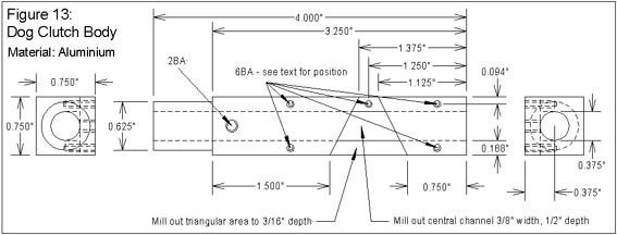
Construction starts with the clutch body (Figure 13); this is a 4" length of 3/4" square aluminium. Centre it accurately in the 4-jaw chuck, face off the ends to length, and turn down 3/4" of its length to a diameter of 5/8". This circular section will carry the Sherline "banjo" parts, after modification as described below. It is then necessary to bore the entire length to 3/8" diameter. This is a non-trivial exercise in the Taig lathe, but it can be done very carefully and with lots of lubrication as the prototype proves. Alternatively, careful set-up on a stand drill might prove more satisfactory it is not essential that the bore is accurately concentric with the 5/8" diameter portion. Mark out, drill and tap the 2BA hole that will carry the input shaft retaining screw. On the same face, mark out and mill the triangular shaped recess for the operating lever to slightly deeper than the thickness of the lever (nominally 3/16") to ensure that it will operate easily when the clutch body is screwed to its bracket. You know when the right depth has been reached, as the cutter will just start to break into the top of the bore. The final milling operation is to open out the bore immediately below this recess to form a slot 3/8" wide to halfway across the bore (1/2" below the surface of the bar). This slot carries the clutch operating shoe, located in the groove in the sliding shaft. Drill and tap the 6 BA hole as marked; screw a short length of 6BA studding into the hole for the slot in the rear end of the operating lever to locate onto. Leave the remaining holes for the present; these are marked and drilled later on in conjunction with the mounting bracket.
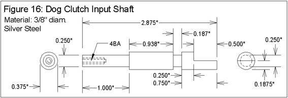
Next, the input shaft. This is fabricated in two parts. The main body of the shaft (Figure 16) is made from 3/8" Silver Steel rod (chosen because of the surface finish, not for any other reason; BMS would do fine). Face off a length to 2 7/8" long. Reduce the diameter over a 1" length to ¼", drill and tap 4BA for the gear retaining screw & washer. Cut the groove for the 2BA retaining screw this groove starts at 15/16" in from the shoulder, 3/16" wide and reduces the diameter to ¼". Remove from the lathe, mark out and mill or file the ½" long flat at the thick end of the shaft. The second part is a bobbin to carry the gearwheels (Figure 19). Three of these are needed in all; one is fabricated and then soft soldered in place on the ¼" diameter portion of this input shaft, the other two are free running gear carriers for use on the intermediate studs in the geartrain. Fabrication is similar to the tumbler output bobbin; turn down a length of ½" diameter stock to 3/8" diameter over a length of 13/16", axially drill ¼" diameter, and part off to leave a ½" diameter shoulder 3/16" long. The groove for the 1/8" square brass key is milled as before, and a 1" length of key soft soldered in position. Clean up the ends and any solder excess, return to the chuck and turn down the key to the ½" diameter; i.e., there should be 1/16" of key protruding above the surface when completed. Solder in place on the input shaft, taking care not to disturb the key in the process, and clean up again. Make the other two bobbins while you are at it!
The sliding shaft (Figure 17) is very straightforward again, silver steel was used; this time the groove is 3/8" wide, and there are two flats to mill/file.
The clutch output shaft (Figure 18) is slightly more involved. Chuck a suitable length of hex section steel bar the one I used measured 0.56" across the flats, which is slightly smaller than a standard 3/8" BSF nut. Face off, axially drill and tap 3/8" BSF (20TPI) to a depth of 5/8". Cut a small shoulder, about 1/32", to the inscribed circle diameter of the hexagon (0.56"). Remove from the chuck, screw the piece onto a short length of 3/8" BSF studding, and use this as a stub mandrel to hold the piece for the remaining machining operations. Mount the mandrel in the chuck so that the end of the hex rod buts against the chuck jaws; the turning action will tend to tighten it against the jaws. Turn down and face off to leave a ¾" long hex shoulder, and a ½" length of 3/8" diameter. File or mill the flat for the last 3/16" of its length. Using the studding as a mandrel in this way ensures that the 3/8" bearing diameter will be as near as possible to being concentric with the leadscrew.
The remaining components of the clutch are the shoe, the lever and the bracket. The lever (Figure 14) is straightforward cut a 1 ¾" length of brass, 3/8" X 3/16". Radius the ends. Drill a ¼" hole through ½" from one end. Cut a 1/8" wide slot in the same end, to engage with the 6BA pivot pin in the clutch body.
The shoe (Figure 15) is cut from a length of 3/8" square section brass. Centre a 1" length in the 4-jaw chuck, turn down one end to ¼" diameter over a length of 3/16" (this fits in the hole in the lever). Remove from the chuck and cross-drill the bar 3/8" from the end of the turned section. Carefully cut and file across this hole so as to leave a semicircular bearing surface that will engage with the slot in the sliding shaft. File the two bevels these are necessary to allow full left and right travel of the shoe in the slot in the clutch body.
Finally, cut a 2 ¾" length of 1"X1"X1/8" Aluminium angle to form the support bracket. The clutch can now be assembled and tested for correct operation. Insert the clutch components, fit the 2BA retaining screw, locking it with a nut so that the input shaft is captive but can rotate freely. Make sure that the clutch will engage and disengage correctly, adjusting if necessary.
The next stage is to fit the clutch to the lathe. The objective here is to end up with the axis parallel to the axis of the lathe, and the shoulder of the input shaft bobbin in the same plane as the corresponding shoulder of the tumbler output bobbin. I.e., if a gear were to be placed on each bobbin, butting against the shoulder, both wheels would be in the same plane. For reasons that will become apparent later, a secondary objective is to allow the input shaft bobbin to overhang any mounting board or bench, to make room for large gears. A word about lathe mounting is therefore appropriate at this point.
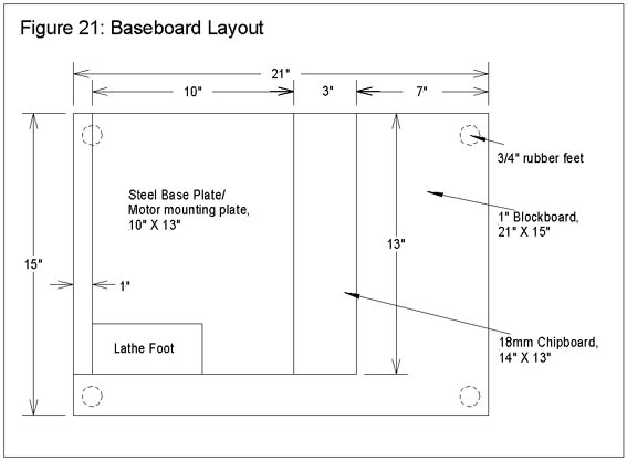
My lathe is mounted on a 10" X 13" steel base plate approximately 1/8" thick that also carries the motor hinge plate; the foot of the lathe is placed in the near left-hand corner of this plate. In turn, the plate is screwed to a 14" X 13" piece of chipboard and nominally 18mm thick. The left-hand edge of the plate is about 1" in from the left-hand edge of the chipboard. In turn, the chipboard is screwed/glued to a 21" X 15" piece of 1" thick blockboard, leaving a 2" apron in front and about 7" to the right of the chipboard. The whole assembly is mounted on ¾" high rubber feet. See Figure 21 for a rough plan of the baseboard. The net result is that the metal base plate for the lathe is raised by about 2.5" above the bench top on which the lathe sits. This gives ample overhang at the left hand side of the lathe to accommodate the change wheels, and provides a useful base for mounting the right hand end leadscrew bearing in a position that will allow the saddle to be removed without disassembly of the leadscrew components.
Mounting the clutch is a matter of careful measurement and marking out. Firstly, determine the lateral distance between the left hand end of the lathe foot and the plane of the shoulder on the tumbler output bobbin. This gives the desired position of the input shaft bobbin's shoulder relative to the lathe foot. The support bracket should be placed so that its right-hand end will match the position of the right-hand end of the clutch body. Place it in position, with its lower edge resting on the mounting plate under the foot of the lathe. Mark out and drill the 4BA clearance holes; spot through these onto the foot itself, drill & tap the foot 4BA. The bracket can now be screwed into position. The clutch body is then clamped temporarily to the bracket, leaving 1/8" clearance at the back of the clutch between it and the bracket carefully checking its alignment relative to the tumbler output bobbin. Place register marks on the clutch and bracket, unscrew the bracket, clamp the clutch and bracket together so the register marks match, and drill clutch and bracket in one operation for the four 6BA mounting screws. Use the tapping drill to the full depth through both pieces; then at the same setting, open out to 6BA clearance through the bracket. This ensures that the components will re-assemble in the right place.
The bracket can then be replaced in its final position, and the clutch fitted to it with suitable screws. If desired, the free end of the bracket at the left-hand side can be supported further by means of a simple angle bracket screwed to the baseboard.
Photo 5 gives an overall view of the leadscrew and its components. The leadscrew is a length of 3/8" BSF studding, giving 20TPI. One end screws into the threaded portion of the clutch output shaft; the other end has an end nut attached (shown in Figure 23), which is located in a simple aluminium bracket that carries the leadscrew thrust bearings. A handwheel is attached to the right hand end of the leadscrew.
Photo 5: Overall view of leadscrew
The studding chosen for the leadscrew should be as straight as possible. I managed to obtain two different samples, both of which proved to be slightly bent on close inspection. However, with careful straightening, I found that it was possible to produce a length of, say 18" long, that was straight enough so that any remaining inaccuracy was not visible to the eye on final assembly. The use of a suitable flat surface helps a lot in determining how straight (or otherwise) the studding is, and in making any necessary corrections.
The actual length of studding required will depend upon the chosen layout; as indicated earlier, I chose to place the right hand bracket sufficiently far beyond the end of the lathe bed so that it does not prevent removal of the saddle when the leadscrew is installed. An alternative would be to devise a way of attaching a bracket to the right hand end of the lathe bed. If you attempt to do this, and the attachment method requires holes to be drilled in the lathe, it is worth remembering that the aluminium extrusion that supports the lathe bed is filled with a concrete-like material!
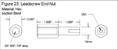
Construction of the end nut is very similar to the technique described for the clutch output shaft. The same 0.56" AF Hex section steel was used, and the same procedure, using a short length of studding as a mandrel, employed to ensure that the plain-turned portion is near enough concentric with the threaded socket. The nut has an axial 2BA-threaded hole in it that will provide a means of adjusting end play in the thrust bearings.
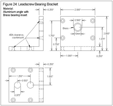
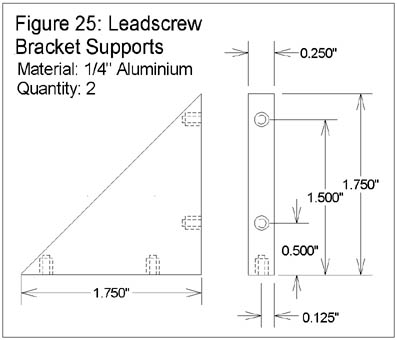
The leadscrew bracket is shown in Figure 24. It is fabricated from a 2" length of 2"X2"X1/4" aluminium angle, with two triangular supports (Figure 25) added in order to make sure that it is suitably rigid. The supports are held in place using 4BA countersunk screws, and the base of the bracket is drilled for 3/8" bolts that will attach it to the baseboard of the lathe. The only difficulty in construction is deciding where to drill the hole for the bearing for the end nut. Careful measurement is required here, backed up with the use of washers under the bracket to adjust its height if necessary. The bearing itself consists of a ½" diameter plain brass or phosphor bronze bearing, bored 10mm diameter, inserted in the bracket and supported by a pair of needle roller thrust bearings, one placed either side of the bracket. The brass insert is a simple turning job from ½" diameter stock, and is a press fit in the bracket. The roller bearings are about 23mm in diameter, bored 10mm, and about 4mm thick; each bearing consists of three components - a roller cage and a pair of steel washers. The roller bearings can be obtained from Electromail (Ref 7) (the mail order arm of RS Components), part number 198-8850.
The bearing arrangement described here is a little excessive for most uses; it may be felt that a plain bearing will suffice, as is used on many commercial leadscrews. However, the arrangement described works very well, and one of my guiding thoughts was that I might be tempted later on to convert the lathe to CNC operation, where the ability to completely remove end play would be useful. (See Richard Bartlett's series of articles on CNC machining, the first part published in issue 41 of Model Engineers' Workshop).
When locating the bracket on the baseboard, care needs to be taken to ensure that the bearing is positioned such that the leadscrew will be parallel to the lathe bed when finally fitted. Drilling the mounting holes in the baseboard slightly oversize will help here, allowing some adjustment of the final position of the bracket. Once the bracket is mounted in place on the baseboard, the leadscrew can be cut to its final length. First, screw the clutch output shaft onto one end of the leadscrew, and soft solder it in place. Apply a little flux to the two parts and drop a couple of short lengths of solder wire into the threaded socket prior to screwing the two components together, heat the joint and apply more solder when the joint has heated up. An alternative would be to use Superglue as a retainer. Next, fit the end nut to the other end of the length of studding and measure the distance between the shoulders on the two end nuts. Now measure the distance between the thrust face of the leadscrew bracket and the end of the dog clutch body. The difference between these measurements, and a bit to allow for the thickness of one of the needle roller bearings, tells you how much to shorten the length of studding. Cut off the excess, screw a 3/8" BSF nut onto the end, followed by the leadscrew end nut. The BSF nut is used as a lock nut, allowing fine adjustments to the screw length to be made once all is properly aligned.
It is now possible to fit the leadscrew in its final position. Unscrew the clutch body from its bracket, fit one of the roller bearings over the end of the leadscrew, and then fit the end of the leadscrew into its bracket. Fit the dog clutch body over the other end of the leadscrew, and screw it back in place on its bracket. The final position and height of the leadscrew bracket can now be adjusted, to ensure that the leadscrew will run parallel to the axis of the lathe in both the vertical and horizontal planes. Tighten the mounting bolts of the bracket, then adjust the end nut and its lock nut to remove all but a couple of thou of end play between the clutch output shaft and the clutch body.
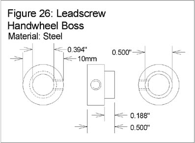
The final leadscrew component is the handwheel. This serves two purposes; firstly, the obvious one of allowing the leadscrew to be turned by hand, and secondly, it provides the end play adjustment for the leadscrew thrust bearings.
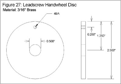
The handwheel boss, Figure 26, is machined from ¾" diameter steel bar. A short length is faced both ends for a final length of ½", bored 10mm to fit the end of the leadscrew end nut, and 3/16" of its length turned down to ½" diameter. A radial hole is drilled and tapped 10-32 UNF to take a grub screw. The handwheel disc, Figure 27, is a 2.5" diameter brass disc, bored ½" at its centre to take the boss, and with a hole near the edge tapped 4BA to take the handle. The disc is soft soldered or Superglued onto the boss, the excess cleaned off and the handle fitted. The handle is simply a 5/8" length of brass rod, slightly waisted, and axially drilled 3.6mm to clear a 4BA domed head brass screw. The screw is passed through the handle, a 4BA nut Superglued in place so that the handle spins freely, and the completed handle is then screwed into place on the handwheel (Ref 8). Any excess bolt length can then be cleaned off at the back of the handwheel. The final finishing touch to the handwheel is to mark 50 divisions on its circumference, corresponding to thousandths of an inch of travel of the saddle. This is relatively easy to do once the banjo components have been modified (see below), allowing a train of changewheels to be attached to the spindle. Choosing suitable combinations of wheels, it is possible to index the headstock, using a detent located between gear teeth to stop the rotation at each 1/50th of a revolution. A scriber mounted in the tool post is used to score the edge of the wheel a short line for the intermediate marks and a full width line for every fifth mark. A set of small number punches can then be used to number every 5th mark. Clearly, you have a choice as to which way you number the marks ascending numbers indicating left hand travel, or vice versa remembering of course that if a conventional right hand thread is used, the direction of saddle travel will be the reverse of the conventional "sense".
The second needle roller bearing and the completed handwheel are fitted to the end of the leadscrew, and any end float in the bearings is removed by means of a 2BA screw and washer screwed into the end of the end nut. The grub screw fitted to the handwheel boss is then tightened to hold the wheel in place.
The Split Nut Assembly
The arrangement described so far leaves 3/8" or so of clearance between the lower edge of the saddle casting and the top of the leadscrew. The split nut assembly is attached under the left-hand end of the saddle casting (see Photo 6). The attachment involves a certain amount of modification to the saddle, in order to provide a flat base for the split nut mounting plate, and also to allow an operating lever to protrude through the side of the casting.
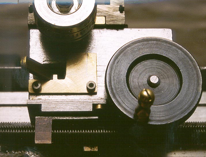
Photo 6: Attachment of Split Nut assembly
I must thank David Gingery for the idea behind the split nut design; the one described here operates in the same manner as the one he used in his lathe design, as described in his excellent series of books, "Building Your Own Metal Working Shop From Scrap" (Ref 9). Instead of the more conventional clamping action found in most lathes, the split nuts in this design are offset from each other, and are part of a carrier that is rotated to disengage them from the leadscrew. The prototype literally used two halved 3/8" BSF nuts, offset by about ½" and soft soldered onto a piece of 1/16" steel plate to which was attached the operating shaft. This worked just fine, but was a little crude and potentially not terribly robust, so the final "production" version was redesigned and involves machining the nut halves and carrier in one piece from ¾" square steel bar.
The final dimensions chosen for the split nut will depend upon the precise positioning of the leadscrew, and in particular, the distance between the top surface of the leadscrew and the underside of the split nut carrier plate (Figure 33) when the plate is fitted in position. Hence, it is advisable to make and fit the carrier plate first. This is machined from a rectangle of ¼" thick steel, 1 ½" X 1 1/8". The 3/8" diameter hole will take the split nut pivot; the elliptical holes are used to mount the plate under the left-hand front edge of the saddle. The two short edges of the plate are thinned to 0.1" over a ¼" width in order for the mounting screw heads not to foul the split nut. The 3/8" hole is nominally centred ½" from the edge of the plate; however, this dimension should be varied according to the position of the leadscrew. Measure the horizontal distance from the front face of the saddle to the axis of the leadscrew and use that as the distance for the centre of the hole. The elliptical mounting holes will allow corrections to be made later if necessary. The underside of the saddle casting should be filed or milled to form a flat, horizontal surface to mount the plate on. Spot through the elliptical holes onto the under edges of the casting for three 4BA tapped holes; these will take cheese head or cap head screws to mount the plate in position. Place the holes so as to allow for fine adjustment of the plate position on final assembly.
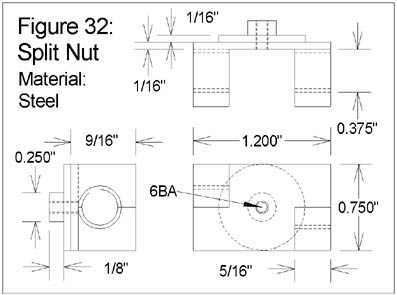
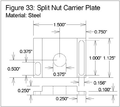
Figure 32 shows the split nut. Machining commences by facing off both ends of a piece of ¾" square steel stock to a finished length of 2.2", and axially drilling and tapping it 3/8" BSF. The hole is drilled slightly off centre; the centre of the hole is shown as 5/16" from one face, and 3/8" from each of the two adjacent faces. Setting up and drilling this offset hole is straightforward in the 4-jaw chuck. Still using the 4-jaw, the ¼" diameter spigot is turned on the face that is furthest from the axial hole. The spigot is 1/8" long. A ¾" diameter pad is turned on the same face while the piece is still in the 4-jaw; finally, the spigot is drilled and tapped 6BA. The piece is then milled (or very carefully filed) out to form the two split nuts, as shown in the diagram (See Photo 7). I had the advantage of being able to use one of the new Taig CNC mills to do this, but it should also be possible using the vertical slide. Milling continues until there is 1/16" of material left at the thinnest part of the "carrier" plate (1/8" thick under the ¾" diameter pad). At this point, if the work has been done accurately so far, the threads should be barely visible on the areas that have been milled out. The dimensions quoted here are based on the assumption that the distance between the carrier plate and the leadscrew is 1/8", as was the case in my prototype. If the measured distance proves to be greater than this, adjust the thickness of the "carrier" plate either by changing the positioning of the threaded hole (i.e., move the hole further off-centre) or turn down less of the back of the nut (i.e., leave a shorter spigot, and thicker pad). The function of the spigot is merely to locate the nut relative to the shaft that it is mounted on, so can be as little as 1/16" long if need be. If there is much more space than can be accommodated by these adjustments, then try starting from larger stock. Clearly, if you find that there is less than 1/8" clearance below the plate, then it is straightforward to remove more material from the base of the saddle casting to make room.
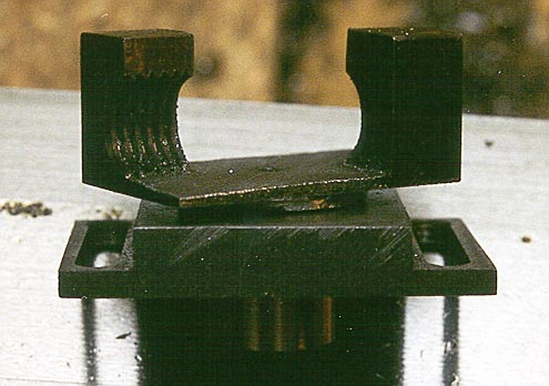
Photo 7: Split nut detail
The split nut is pivoted through the hole in the carrier plate by means of a brass pivot (Figure 34). This is turned down from ½" brass bar; first turn ¼" of its length down to 3/8" diameter the intent is that this should be a close "running" fit in the hole in the carrier plate. Also, the length of this section should be adjusted to very slightly more than the thickness of the carrier plate, so that the pivot and nut will turn freely, but with minimal play, once assembled. Bore through to clear a 6BA bolt (2.8mm), then counterbore 1¼" diameter to a depth of 1/8" to take the full depth of the spigot. Check that the spigot goes fully home. Part off, reverse and finish to a total length of ½"; counterbore from the ½" diameter end, aiming to leave a shoulder of about 1/16" of metal. Drill for a 3mm (or equivalent size) grub screw.
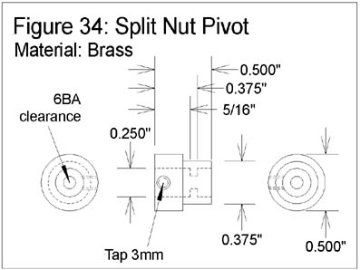
The mounting plate, split nut and its pivot can now be assembled. Push the thin end of the pivot through the hole in the mounting plate, from what will be the upper face when assembled (the non-rebated face). Push the spigot home from the other side. Fit a 6BA cap head screw through the hole in the pivot, and tighten the assembly. Check that the split nut pivots freely and that there is minimal play; adjust the pivot length if necessary.
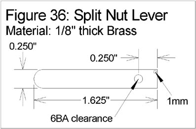
The final components are the split nut boss (Figure 35) and the split nut lever (Figure 36). The latter is simply a length of ¼" X 1/8" brass, with a pivot hole drilled to take a 6BA screw, and a small (1mm diameter) hole. The latter hole will take a small spring, such as the ones that are found in retractable ball-point pens.
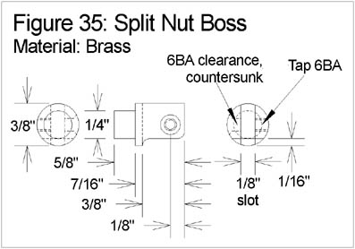
The boss is turned from 3/8" diameter brass. Reduce it to ¼" diameter over a length of 3/16" and part off to a total length of 5/8". Cut a 1/8" wide slot in the fat end, to a depth of 3/8" to take the lever. Cross drill with a 6BA tapping drill, then open out one half to clearance size (2.8mm) and countersink. Tap the other half 6BA. File off the "back" of the boss, removing about 1/16" of material. The lever can now be fitted, with the short end protruding from the "back" of the boss, and pivoted on a 6BA countersunk screw. Make up a short spring, using a ball-point pen spring or similar, so that the overall length is approximately ½" and there is a loop at either end. Thread one end through the 1mm hole in the operating arm.
The final operations involve cutting a slot in the front face of the saddle to allow the operating arm to protrude through from the back of the saddle. The slot needs to be about ½" long, with two notches about 1/8" deep in the lower edge. The notches locate the operating arm in the engaged and disengaged positions and therefore need to be cut at an angle; the best approach is to cut the slot first, test assemble the lever in position and mark out the positions for the notches. The position of this slot should be such that the arm is horizontal when it is located in either notch; i.e., cut the slot so that the bottom edge of the two notches is approximately 9/16" above the upper face of the carrier plate. Note that to disengage the split nut, the arm does not need to move very far, and that care should be taken to ensure that when in the disengaged position, the split nut does not foul the foot of the lathe when the saddle is near the headstock. I found that the "land" between the two notches needs to be no more than 1/8" wide in order to allow the nut to disengage properly and not to foul the foot - see Photo 6. You will also notice from this photo that much trial & error with this arrangement forced me to cover up earlier attempts with a small brass plate that carries the final notches this may prove to be a good solution for others as well!
Final assembly of the split nut involves fitting the arm and boss to the split nut pivot and locating it with the grub screw so that, when the operating arm is in the engaged (furthest left) position, the split nut aligns with the axis of the leadscrew. In order to access the grub screw, this can only easily be done with the saddle removed from the lathe. It is necessary to provide a means of locating the free end of the operating arm return spring inside the saddle casting. The simplest approach here is to drill a 2.8mm (6BA clearance) hole through the left-hand end of the saddle, about ½" down from the top edge and ½" in from the front. A 6BA screw and nut can then be used to locate and tension the spring. Once in position and tensioned, the spring should be just strong enough to keep the operating arm located in the notches.
Loosen the carrier plate's mounting screws so that the plate can be adjusted for alignment, and re-fit the saddle with the operating arm in the disengaged position. Check the operation of the split nut, adjusting the position of the mounting plate as necessary. The aim here is to ensure that, when the nut is in the engaged position, it does not deflect the leadscrew from its normal axis. You may find that a small amount of filing inside the saddle casting is necessary in order to allow the carrier to be correctly located and for the pivot not to bind against the wall of the casting. Finally, tighten the mounting plate screws.
At this point, it should be possible to engage and disengage the split nut, and to drive the saddle via the leadscrew handwheel.
The "banjo" arrangement used in the Sherline kit is slightly unconventional, partly due to the fact that they always use 60 DP gears for the first driver and driven wheels. Two aluminium brackets are provided; the main bracket (Figure 28) mounts on a boss at the left hand end of the leadscrew, and in the normal Sherline set-up, the auxiliary bracket (Figure 29) mounts on the far end of the first. Rather than make a purpose built banjo from scratch, I decided to retain the Sherline parts and modify them to suit the new application. The main bracket, in this application, will mount on the turned section of the dog clutch body. The diagrams show the modified versions of these components; Photo 8 shows the components alongside the studs made for use with them. The resultant banjo allows a more (but not completely) conventional arrangement. For many gear trains, the fine feed set-up described below being an example, only the main bracket is required; however, the auxiliary bracket allows a wide range of configurations to be supported. For those who choose not to use the Sherline parts, both of these brackets can be easily constructed from aluminium, brass or steel strip.
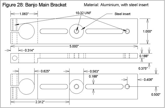
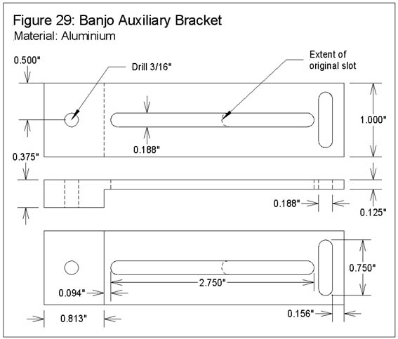
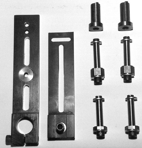
Photo 8: Banjo components and studs
The main bracket starts out with a 5/16" diameter hole and a 10-32 UNF pinch bolt at one end; a UNF 10-32 threaded hole at the far end, and a 9/16" hole about half way between. The pinch bolt end of the bracket is 3/8" thick; the remainder of its length is milled out at the back of the bracket to half that thickness. The modifications involve cutting the two oval slots shown in the diagram, both 3/16" wide, and filling the central hole with a steel insert, drilled/tapped 10-32 UNF at the centre. The insert is a press fit, assisted with Superglue for good measure. If making a bracket from scratch, don't bother with the central threaded hole; simply form one slot by joining the two shown. (It might make sense not to bother with the other threaded hole either simply extend the slot to where the hole is. Also, I would probably not bother to mill the bracket to half thickness much easier to leave it at 3/8" thick for the whole of its length.) The slot lengths are not critical the one nearest the pinch bolt end is about 1" long, the other about 1.5" long.
The auxiliary bracket is 4 1/16" long, 3/8" thick for the first 13/16" of its length, and 1/8" thick for the remainder of its length. If making up one of these from scratch, there is little point in retaining the thickened section; use a length of 1/8" thick material. There is a pair of slots in the thin end, arranged in a T, and a 3/16" hole at the thick end to take a 10-32 UNF bolt. The modification to this part involves extending the longitudinal slot towards the thick end; the resultant slot is 2.75" long.
The final components for use with the banjo brackets are the long and short studs, Figure 22. These differ only in the length of their bases; the short studs mount directly on the main banjo bracket and the long studs mount on the auxiliary bracket. The auxiliary bracket is mounted on the "back" of the main bracket (it is mounted using either of the two threaded holes, with a 10-32 socket head bolt through from the back). Hence, the long stud needs a base that is 3/16" longer than the short stud, in order for the shoulders of these studs to be in the same plane when the banjo is in use. Photo 9 shows the auxiliary arm mounted on the main arm, with both types of stud fitted.
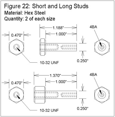
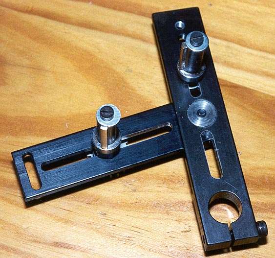
Photo 9: Banjo assembled
The studs are turned from hex section steel nominally 0.470" across flats, but this dimension is unimportant. They consist of a plain-turned section that is nominally 1" long, drilled and tapped 4BA, and a hex section shoulder that is drilled and tapped 10-32 UNF. As before, the hex section is relieved to present a circular section to the bracket on one side, and the bobbin on the other. The 1" length should be just a couple of thou longer than the length of the bobbins, to ensure that the bobbins run freely on the studs when held in place with 4BA retaining screws and washers.
The moment of truth has now arrived the leadscrew is in place, along with tumbler reverse, dog clutch and split nut, and the banjo components have been constructed or modified, so all that remains is to install some wheels and see what happens.
The leadscrew is 20 TPI, or 50 thou of saddle movement per revolution. Given the size of the lathe, it will generally be the case that its cutting tools will have small tip diameters, and hence, it is highly desirable to employ a really fine feed. In order to achieve this with a small number of gear wheels, I decided to use an overall reduction ratio of 24:1 as the fine feed, achieved by using two 20T driver wheels, one 80T and one 120T driven wheels. This ratio gives a saddle feed of a touch over 2 thou per spindle revolution, which seems to work quite well.
The 20T wheels are again HPC part number G-24-20-PG, the 80T and 120T wheels are part numbers G-24-80-PG and G-24-120-PG respectively. The 120T wheel is a monster, approximately 5" in diameter, and needs to be used as the final driven wheel, held on the clutch input shaft. This is one of the major reasons for allowing suitable "overhang" at the left hand end of the lathe, as this wheel hangs well below the lathe foot. In order to make use of these wheels some modification is necessary. The 20T wheels come with a bore size of 0.3125", which needs to be opened out to 3/8" using the techniques described above. Having done that, all four wheels need a 1/8" wide keyway cut in the bore. The easiest way to do this is to drill a 1/8" hole as close to the bore as possible and to open it out by careful filing. The wheels should then fit nicely on the various bobbins already constructed.
The fine feed set-up needs just the main banjo arm, fitted with a single short stud and bobbin by means of a 10-32 UNF socket head bolt from the back of the arm. First, fit one 20T wheel to the tumbler output bobbin, retaining it with a 4BA screw & washer. Fit the 80T wheel and second 20T wheel to the stud, using a spacer of a suitable thickness between the two wheels. Suitable spacers can be made up very simply by cutting washers of varying thicknesses (for example, 1/8", ¼" and ½" will prove useful for various configurations), with a 3/8" hole, and a keyway cut as described for the wheel modifications. Fit the Banjo arm to the clutch body and adjust the position of the stud to make it possible to fit the 120T wheel to the clutch input bobbin. It will be necessary to insert more spacers onto the bobbin before the 120T wheel; it should be fitted so that it is flush with the extreme end of the input shaft. Retain the 120T wheel with a 4BA screw & washer. Adjust the stud position so that the 20T wheel meshes nicely with the 120T wheel, and tighten up its 10-32 UNF bolt. The banjo can then be rotated up until the 80T wheel meshes nicely with the 20T wheel on the output of the tumbler, and its clamp nut tightened. Photo 10 shows the fine feed installed and ready to go.
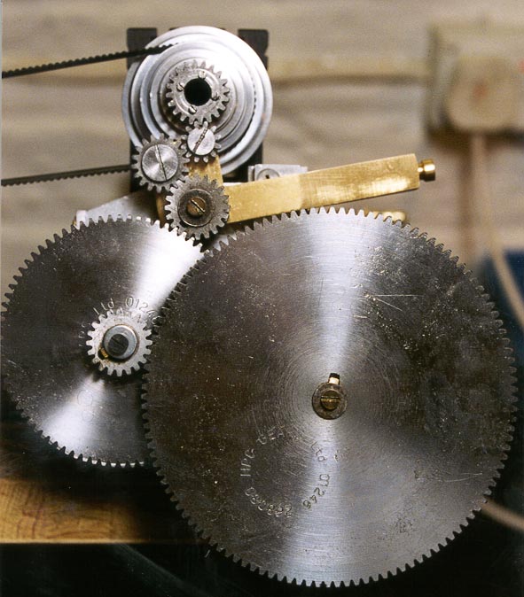
Photo 10: Fine feed setup
At this point, it is advisable to make sure that all bearing surfaces are liberally lubricated, especially those that involve steel-to-steel contact, such as the bobbins and idler wheels.
Disengage the split nuts, set the tumbler in neutral, engage the dog clutch and make sure that all operates smoothly by hand. Engage the tumbler and switch on the lathe. The leadscrew should rotate nicely. Check that the clutch can be operated while the lathe is running; if not, polishing the D sections of the shafts may help. Try engaging the split nuts. This should not be forced; if all is nicely aligned, the nuts will click into place quite easily with a little rotation of the leadscrew, and the handle should be kept seated in its slot by the spring tension. If all is well, you are ready to use powered fine feed on your Taig for the first time.
Obviously, the choice of gears described here is only one possible fine feed configuration; the use of a second stud opens up the possibility of using smaller wheels, albeit having to use 6 rather than 4. One of the considerations, however, was that the 120T wheel seems like a useful wheel to have around in order to use the change wheels as the basis of dividing operations in the lathe. Another observation here is that if these wheels are to be used only for fine feed (i.e., if you do not intend to intermix them with the Sherline wheels for any operations), then there is no particular need to stick to 24DP. The essential requirement is for the bore, keyway and thickness of the wheels allow them to be fitted to the bobbins. Equally, there is no particularly good reason why a fine feed shouldn't be configured using suitably sized pulleys and belts rather than gears, again as long as they can be fitted to the bobbins. In fact, pulleys and belts are in some respects more desirable, as they produce a lot less noise!
With the fine feed set-up described, it is quite acceptable to engage/disengage the split nut and the dog clutch while the leadscrew is rotating; however, it is extremely inadvisable to try operating the tumbler while the lathe is running.
This is achieved in a similar manner to the fine feed set-up. For many, if not all, of the screw pitches that you will want to use, the 24DP wheels in the Sherline kit can be used, and can be combined with the 24DP wheels used for the fine feed configuration. The banjo arrangement allows a wide range of configurations to be used; if necessary, further bobbins can be made up in order to allow more than 2 intermediate studs to be used if this proves to be necessary.
The 60DP wheels provided in the Sherline kit are one 50T two 100T and one 127T wheel. These wheels can obviously only be used as a matched driver/driven pair, as they cannot mesh with the other wheels. Clearly, using both 100T wheels is not very interesting as it is easier to omit them altogether, and the 50T/100T combinations provide ratios of 1:2 or 2:1 that can be generated using a 20T and a 40T wheel (or 40T and 80T) from the 24DP set. Hence, it will almost certainly only be necessary to use the 60DP wheels if you wish to make use of the lathe to cut metric threads, using the 127T wheel in combination with a 50T or 100T wheel. In order to make use of these wheels it is necessary to adapt them to fit the bobbins. As supplied, they have a 9/16" bore and a keyway that is about 7/32" wide. These need to be reduced to give a bore size of 3/8" with a 1/8" wide keyway. The simplest approach here is to turn a length of steel tube, with a 3/8" bore and an OD that will give a press-fit into the 9/16" bore. The keyway can then be milled or hack-sawed straight through the wall of the tube, leaving it with a "C" shaped section. This can be cut into lengths to form adapters for the 60DP wheels, pressed and/or Superglued in place. I chose to cut these to 5/16" in length, to match the thickness of the HPC gears, but this is not essential. Photo 11 shows three modified Sherline wheels; 50T, 100T and 127T.
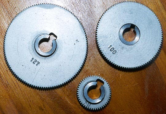
Photo 11: Modified Sherline wheels
The table of changewheel combinations given in the Sherline kit is a suitable starting point for use with this leadscrew. One obvious point is that there is no need to bother with the left hand and right hand thread variants, as the tumbler allows a single set-up to cut either handedness.
The possible change wheel combinations include threads as coarse as 10TPI; a little thought, given that the leadscrew is 20TPI, leads you to the conclusion that, when cutting a 10TPI thread the leadscrew will be rotating twice as fast as the lathe spindle. In the case of my own lathe, the slowest spindle speed attainable is around 450 RPM; hence, when cutting 10TPI under power at the low speed setting, the leadscrew would be doing a cool 900 RPM! I have actually tried this interestingly enough, the experiment was one of the reasons why the tumbler plate is so substantial, as the first version of the tumbler plate operating arm buckled and broke under the forces exerted on it by the gear train! This is almost certainly one of the reasons why Sherline include a substantial, 4" diameter, handwheel in their kit, which is used to hand-drive the spindle at more leisurely speeds. Another reason is that the Sherline kit uses the 60DP wheels in all setups; I doubt whether these are really up to the job of operating under power. Hence, when cutting coarse threads, and when using the metric conversion wheel, running under power is not a good idea.
Similarly, attempting to engage the dog clutch under power, with a coarse screw cutting set-up, is not a smart move the shock load on the gear train when the dog engages is a little disconcerting! However, disengaging the clutch under power is not a problem.
Figure 30 shows an adapter that will allow the Sherline handwheel to be used to drive the Taig lathe spindle, as seen in Photo 12. The handwheel has a 9/16" bore and is fitted with a grub screw; the adapter passes through the handwheel, and is fitted into the 3/8" bore of the Taig pulley and it's attached 20T wheel. A 1.75" 10-32 UNF socket head bolt passes through the adapter, and screws into a conical nut (Figure 31) that expands the end of the adapter to grip the bore. The hexagonal head simplifies tightening the 10-32 bolt.
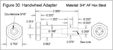
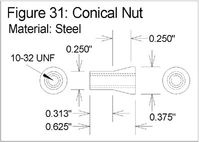
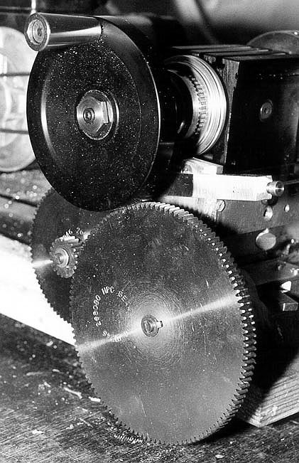
Photo 12: Sherline handwheel fitted to the spindle drive pulley
The adapter is made from ¾" AF hexagonal steel stock. A ¼" shoulder of hexagonal material is left at the head end; the next 1.25" are turned down to 9/32" diameter, and the remaining ½" turned down to 3/8". Drill the piece axially 3/16" diameter, counterbore ¼" diameter to a depth of ¾", and add a slight internal bevel at the thin end. Part off to length, reverse and counterbore 5/16" to a depth of ¼" to take the bolt head. Remove from the lathe, and make two cross cuts in the thin end to a depth of ¼" to allow the collet to be expanded by the conical nut. The latter is a simple turning job using 3/8" steel stock, tapered then drilled and tapped 10-32 UNF.
It cannot be emphasised too strongly that exposed gear trains have infinite ability to attract and consume loose objects, such as ties, hair, fingers and so on. With the fine feed configuration described here, the 24:1 reduction in rotational speed is accompanied by a corresponding increase in torque! Needless to say, getting anything that contains nerve endings trapped in these gears is going to be, at the best, a very uncomfortable experience. Hence, my advice to anyone that builds and uses this design to cover the changewheels during operation at all times. I have not offered a cover design here, as mounting arrangements will inevitably differ according to baseboard layouts and so on; however, it should be a trivial job to fabricate a suitable cover from thin metal sheet, or even thin plywood.
Ref 1 Peatol Machine Tools, 19 Knightlow Road, Harborne, Birmingham B17 89S, UK.
Tel/Fax: 0121 429 1015
Ref 2 Taig Tools, 12419 E. Nightingale Lane, Chandler, Arizona 85249, USA. Tel: (602) 895-6978
Website: http://www.taigtools.com/
Ref 3 Sherline tools and accessories can be obtained through Millhill Supplies, 66/68 The Street, Crowmarsh Gifford, Nr Wallingford, Oxon, OX10 8ES, UK.
Tel: 01491 838653
Website: http://www.sherline.com/
Ref 4 HPC Gears, Foxwood Industrial Park, Chesterfield, S41 9RN, UK.
Tel: 01246 260003 Fax: 01246 260003
Website: http://www.hpcgears.com/
Ref 5 Sumitomo inserts and tools are obtainable from Penco, 3, Greenfield Close, Sheffield, S8 7RP, UK.
Tel/Fax 0114 237 7716
Ref 6 The design is based around a 20 TPI leadscrew in order to keep the thread cutting capability essentially the same as the Sherline lathe. As 3/8" BSF studding, taps etc. may not be readily available outside the UK, it may be appropriate for some readers to choose a different thread for the leadscrew. A suitable alternative here would be 7/16"-20TPI (UNF). There should be sufficient room in the design to accommodate the extra diameter without too much difficulty; clearly, some dimensions may need to change in order to do this.
Ref 7 Electromail, P.O. Box 33, Corby, Northants, NN17 9EL, U.K.
Tel: 01536 204555 Fax: 01536 405555
Website (Radiospares): http://rswww.com/
Ref 8 The standard handles fitted to the Taig cross-slide and saddle traverse handwheels can readily be modified in a similar manner to produce "deluxe" spinning handles that are much more comfortable to use. The standard handles are a press fit in the handwheels; carefully twist them out with a pair of pliers, drill axially, and re-fit with a 4BA bolt and nut as described above. Conveniently, the holes in the handwheels seem to take a 4BA tap without further drilling.
Ref 9 Gingery, David J, "Building Your Own Metal Working Shop From Scrap, Volume 2: The Metal Lathe", ISBN 0-9604330-1-5.
A Leadscrew for the Taig/Peatol Lathe
© Tony Jeffree 1999
All Rights Reserved
Email me at this address...
website ({at}) jeffree.co.uk
Return to Model Engineering Activities page...