Introduction
I have a Myford ML-7 that has been the subject of a couple of articles in MEW - the first when I fitted a Newton-Tesla variable speed 3-phase drive kit, and the second describing the construction of a variant of the George Thomas headstock dividing attachment, driven by a stepper motor, that allows headstock dividing under the control of my DivisionMaster electronic dividing system. The subject of this article, performing a conversion of the lathe to full CNC operation, has been on the project list for a while now, for a number of reasons:
- My lathe had a Myford gearbox attached to it. This is a wonderful and time-saving device, compared with fiddling around with change-wheels, but only if all you will ever want to use it for is fine feeds and cutting standard Imperial threads. The ease of switching between fine-feed and thread-cutting pitches is just great, and if that was all I needed, you probably wouldn't be reading this article. However, as soon as you want to do anything else, such as cutting Metric threads, or (perish the thought!) BA threads, or if you need to cut some strange thread pitch for a worm to mate with a spur gear, you may as well not have bothered with the gearbox in the first place, because you lose the instant change to fine-feed drive, the gearbox itself provides very little help in selecting the feed rate, and you are back to messing around with banjos and change-wheels. In fact, the presence of the gearbox becomes more of a hindrance than a help at that point.
- Once you have set up the change-wheels and/or gearbox appropriately, thread cutting on the lathe is a tedious activity at the best of times, and again, with non-Imperial threads on an Imperial machine, the threading indicator dial is useless, and the only option is to keep the half nuts engaged and wind back after each cut (rather than disengaging the split nuts and re-engage them using the threading dial, as would be possible with Imperial threads).
- For some of the turning operations that I would like to be able to do, it would be very nice to be able to draw the part, press a button, and let the machine take over. Examples would be complex profiles, parts where there is a lot of stock to remove, and parts where I want accurately matching sets (making matching pillars for clocks springs immediately to mind, but I also fancy making a metal chess set at some point.)
- Last but not least, I wanted to demonstrate that going the CNC route can actually be a cheaper option than buying a gearbox and a metric conversion set, even on the used market. So, at the start of this project, I put my gearbox, change-wheels, threading dial, tumbler reverse cluster, leadscrew handwheel, and metric conversion set up for auction on Ebay; the whole lot netted about £550. I haven't dispensed with the top slide yet, but that will become surplus to requirements once the conversion is complete, and will net a further few quid. With entry level PCs getting to be very cheap these days, installing two-axis CNC control on a lathe can be done very readily for that kind of money, and with some change left over; even cheaper on the used market, or if you have an older model PC that you can use for the purpose.
I felt that it would be good to retain the ability just to clamp a piece of stock in the 3-jaw and turn by hand; some operations are so simple to perform manually that you could have done the job quicker that way than going the CNC route. So, I decided to convert the lathe in as non-intrusive a way as I could manage, so that I would retain as much of its manual capability as possible. The changes I have made are very easily reversible if it becomes desirable at some point in the future to change the lathe back to its standard manual specification. I very much doubt that my lathe will ever be converted back to standard ML-7 specification; however, for those readers that would like to give CNC a try but are reluctant to "vandalize" a perfectly good ML-7, the approach I have taken might hold more appeal than a conversion involving rather more extensive work - replacing ACME leadscrews with ballscrews, and so on - where the options for converting back are more limited.
In this first article, I will concentrate on the modifications needed in order to motorize the leadscrew. While not a complete CNC conversion, this conversion can to some extent stand on its own if you use a stand-alone controller such as the Divisionmaster as the drive unit, as discussed later in the article.
Design decisions
I decided that I would attempt a conversion using the existing leadscrew and split nuts. This would allow the saddle to be disengaged from the leadscrew in the normal manner for manual operation. There is nothing inherently wrong with using ACME screws, or even V-form screws for that matter, for CNC applications. Contrary to popular misconceptions, ballscrews don?t provide an instant fix to the backlash problem unless you go for exotic anti-backlash nuts at exotic prices, and similar options are equally available (and similarly expensive) when using conventional screws. The main advantages of using ballscrews are that they are generally much more efficient than conventional screws, and their rate of wear is generally much less.
In any case, with CNC on a lathe, as the majority of operations will involve facing, plain turning to a shoulder, or screwcutting operations, backlash is a lot less of an issue than it would be on a mill, and the use of backlash compensation in software is much more likely to be a useful option in cases where it is important (machining a ball end on a handle, for example).
In order to properly control end float in the leadscrew, and also to reduce the frictional load seen by the motor when driving the leadscrew, the plain bearing at the right hand end of the lathe bed was modified using a variant of the leadscrew thrust bearing system sold as a kit by Hemmingway Kits. With the kind permission of Kirk Burwell at Hemmingway, I will describe how that conversion is performed, and where my version of it diverges from the original design.
The drive system for the conversion is based on stepper motors and microstepping stepper motor drivers, as was the case for my earlier mill conversions. A quick-and-dirty test with a spring balance attached to the leadscrew handwheel suggested to me that one of the large NEMA 23 frame stepper motors that I used in my X3 conversion (MEW issue 113), Arc Eurotrade part number AC571157525M, would very definitely be OK for this job, and that their smaller NEMA 23 motor, part number AC570764525I, might well be powerful enough too. To be on the safe side, I decided to install a 2:1 reduction drive between motor and leadscrew, again using "timing belt" pulleys; the effective doubling in available torque would allow me to experiment with different motor sizes, and using a pulley drive would have the added benefit of allowing the motor to be tucked away neatly behind the lathe bed at the tailstock end of the lathe, so it wouldn?t much matter how big a motor I decided to use.
I went into a fairly lengthy discussion on the characteristics of stepper motors and their drives in my recent Taig mill conversion articles (MEW issues 120 and 121), so I don't plan to repeat that discussion here; the main point to bear in mind is that with "chopper" drive systems, the higher the supply voltage you use, the higher the top speed you can expect from the motor. The stepper motors mentioned above are rated at 2.5A/phase, so in principle, either of the stepper drives sold by Arc Eurotrade are contenders for driving these motors (as are many other stepper drives - Xylotex and Geckodrive for example); however, having had very satisfactory results with the Arc drives on my previous conversions, I decided that I would stick with them. The choice then comes down to which one - the smaller drive has a max voltage rating of 40V while the bigger drive handles up to 80V. I decided to put off the final choice until I had tested the drive system for the leadscrew and seen just what it was capable of in practice rather than on paper.
Modifying the leadscrew
My starting point with this conversion was a lathe that had been stripped back to its simplest form - i.e., it had no QC gearbox, and the change-wheel train had been removed. For those that want to keep their gearbox in place, it is certainly possible to do that, although the gearbox does place a small amount of drag on the drive system even when it has been put in neutral - the final drive gears to the screw are permanently engaged. Similarly, as there is no dog clutch on a Myford, the change-wheel train in a non-gearbox lathe is permanently connected to the leadscrew even if the tumbler is in neutral. The downside here is that the extra drag may reduce the slew rates possible with the conversion, but this shouldn't be a significant issue. If you decide to keep the gearbox and/or change-wheels in place to start with, you can always remove them later (replacing the gearbox with the standard support bearing at the headstock end, of course) once you have discovered that actually, you don?t use them anymore anyway!
The first stage is to modify the bearing at the tailstock end of the lathe, using the Hemmingway kit (HK 1470) as the starting point. This conversion essentially adds a pair of needle roller thrust bearings, one either side of the standard plain bearing bracket at the tailstock end of the lathe. These thrust bearings consist of a pair of precision ground washers that sandwich a plate between them that holds a number of radial hardened rollers. The Hemmingway kit encloses these thrust bearings in a pair of dust caps to prevent ingress of swarf etc., and also sleeves the end of the leadscrew to ½" diameter to match the ID of the bearings.
The starting point for installing the thrust bearings is to remove the bearing support bracket from the tailstock end of the lathe. To do this, you remove the Nylock nut from the end of the leadscrew, take off the handwheel (if you have one) or the thrust collar (if you don't), and remove the drive peg from the leadscrew. The bearing bracket can then be unscrewed (and the taper pins removed if fitted) and slid off the end of the leadscrew, and the setscrew collar removed from the leadscrew. Now face off the two thrust faces of the bracket to remove any scoring that may be there. Photo 1 shows this operation in progress; I have an accurately centred 3-jaw chuck on my lathe and found that I could mount the bracket directly in the chuck as shown, with minimal runout on the bore. If you are not so lucky, then it may be necessary to use a 4-jaw and clock the bore for concentricity. Take a facing cut across each end of the bracket, sufficient to clean up the faces to a diameter slightly greater than the nominal 1" diameter of the dust caps.
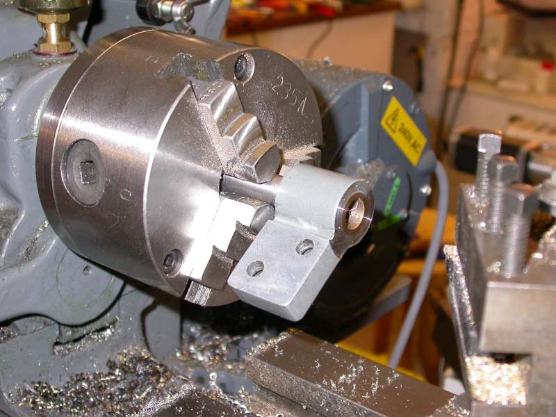
Photo 1: Facing off the leadscrew bracket
The second operation to perform on this bearing bracket is to bore out its existing bronze bearing bushes to accommodate the ½" OD sleeve that will be fitted to the leadscrew end (Figure 1). The Hemingway kit suggests machining a pair of new bushes, pressing out the old ones, and pressing in the new, then reaming them ½"; this seemed too much like hard work to me, so instead, I bored and reamed the existing bushes to ½" diameter in the lathe, as seen in Photo 2.
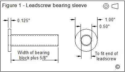
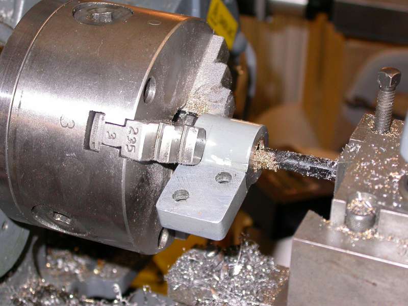
Photo 2: Boring out the bronze bush
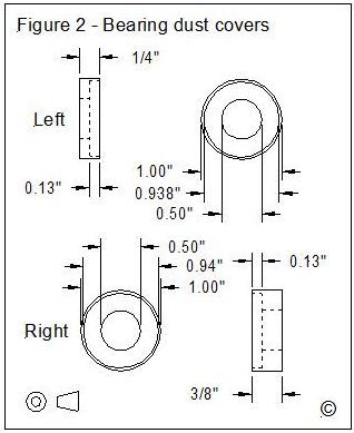
The sleeve is then machined to the dimensions shown in Figure 1 from a piece of 1" diameter steel bar. The ID of this sleeve should be a close fit on the machined end of the leadscrew - nominally 7/16" - but measure your particular leadscrew for an accurate fit. The OD needs to be a running fit in the bronze bearing bushes. The length of the ½" diameter portion of the sleeve should nominally be 5/8" longer than the measured distance between the two thrust faces on the bearing bracket. The intent here is that the ½" diameter portion of the sleeve should be slightly shorter than the combined lengths of the end caps with thrust bearings fitted, plus the bearing block.The two dust caps are machined to the dimensions shown in Figure 2, again from 1" diameter steel bar. These caps basically differ only in their length. The recess in each cap is bored to a depth of 0.13" and to a diameter of 0.938", so that a thrust bearing will fit in the recess with its outer washer just slightly proud of the cap. A little undercutting at the corner of the recess is advisable to ensure that the thrust bearing lies flat against the inside of the cap. In the Hemmingway kit design, the sleeve and the thinner of the two caps (the one marked "Left" in Figure 2) are drilled for a drive pin that connects them together; I opted for the far simpler approach of permanently fixing the cap in place on the sleeve with Loctite 326 Structural Adhesive, although Superglue would have worked just as well. Simply slide the cap along the length of the ½" diameter portion of the sleeve till it buts up against the flange, and use a drop of 326 or Superglue to hold it in place.
After cleaning and de-greasing the end of the leadscrew and the bore of the sleeve, fit the sleeve to the leadscrew, again with a spot of Loctite to hold it in position. The left-hand needle roller bearing, the bearing block, the right hand roller bearing, and the right hand bearing cap can be fitted in position, in that order. Photo 3 shows the parts at this stage of assembly, with the old thrust collar and nut temporarily re-fitted.
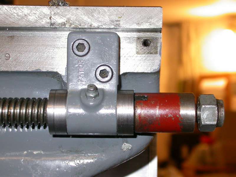
Photo 3: Trial assembly
The next stage is to modify the leadscrew drive pulley. The starting point is a 5mm pitch 40 tooth aluminium timing belt pulley from RS Components (see Parts List); this is modified by increasing the through hole diameter to 5/8" and by boring the outer face to a diameter of 1.375" and a depth of .66". Photo 4 shows this machining operation in progress. If your lathe was fitted with a handwheel, it will be necessary to machine the thrust collar shown in Figure 3 from steel bar; otherwise, the original thrust collar that was removed during leadscrew disassembly is modified to match Figure 3, by reducing the overall length and reducing the diameter of one end to a press fit in the bore of the pulley - nominally 5/8" diameter - over a length of 0.4". The thrust collar is also drilled and tapped radially for a suitable set screw, as shown in the drawing - I had some UNF 10-32 set screws to hand (approx the same size as 2BA) so that is what I used, but anything similar will do. Once the collar has been machined or modified, it is pressed into the machined bore of the pulley on the side with the boss - again, I used a dab of Loctite 326 to make sure that it will stay put permanently. Photo 5 shows the modified pulley with the thrust collar inserted.
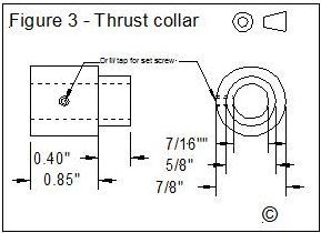
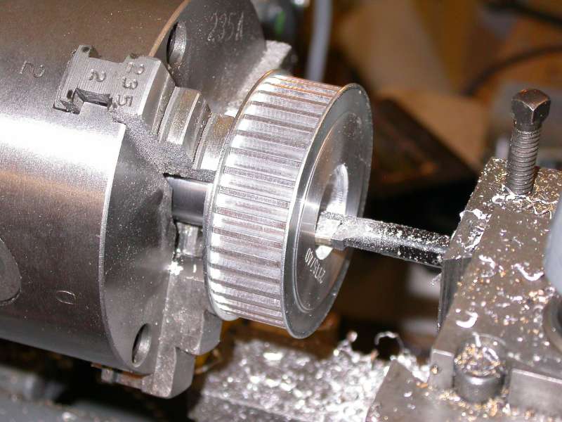
Photo 4: Machining the leadscrew pulley
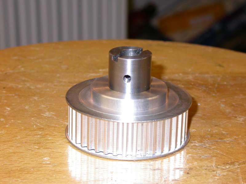
Photo 5: Modified pulley with thrust collar fitted
The pulley/collar assembly can now be test-fitted to the end of the leadscrew, and the set screw screwed down lightly to mark the end of the leadscrew where it will be seated. Remove the pulley and file a flat on the leadscrew end at this point as shown in Photo 6. The pulley can now be re-fitted, the Nylock nut adjusted to take out all end-float in the thrust bearings, and the set screw nipped up firmly, as shown in Photo 7. The leadscrew should now be free running, and have no detectable end-float.
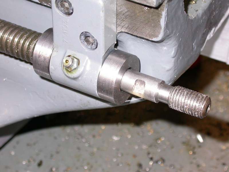
Photo 6: Flat machined for set screw seat
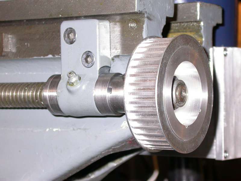
Photo 7: Leadscrew pulley installed
Installing the leadscrew stepper motor
As mentioned earlier, the use of toothed belts and pulleys allows the stepper motor to be mounted to the rear of the lathe bed, nicely out of the way. Photo 8 shows the motor mounting bracket fitted to the rear of the lathe bed - the ML-7 and Super 7 beds have a series of ¼" BSF threaded holes spaced at 4" intervals along the back of the bed for mounting accessories, and these were pressed into service to attach the motor mounting bracket. The bracket is basically an 8.5" length of 3" X 3" X ¼" aluminium angle, with a 3" X 3" square cut out of one end and attached to the other end with three M4 countersunk screws to form an open box. Of course, if you have some 3" X 3" material to hand, then you can use that rather than cutting a section out of the angle. The 3" X 3" plate is machined to allow the motor to be mounted and its position adjusted - NEMA 23 motors have a central register 1.5" in diameter and four mounting bolt holes on their mounting flanges, and the mounting plate is machined with elongated holes to allow the belt to be properly tensioned. These holes are dimensioned to take M6 bolts; the bolt holes in the motor should be drilled and tapped M6 as this avoids the impossible job of having to fiddle around with nuts in the confined space between the motor bracket and the lathe bed. I used four slot-headed M6 screws with washers behind the screw heads to mount the motor.
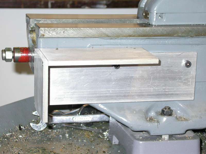
Photo 8: Motor mounting bracket installed
The dimensions of the motor bracket are shown in Figure 4 and the motor mounting plate in Figure 5; Photo 9 shows the mounting plate being machined on my X3 CNC mill. I found that this arrangement didn?t give quite enough adjustment for the length of the timing belt, and there wasn?t a stock belt size from RS that would suit, so I used a pair of standoffs 3/8" thick between the angle bracket and the lathe bed - these were just offcuts of 3/8" X 1" bar from the scrap box with ¼" holes drilled in them. Photos 10 and 11 show the motor in position, with motor pulley and belt fitted. The boss of the motor pulley needs to be drilled and tapped for a setscrew, and the position of the pulley on the motor shaft adjusted so that the two pulleys are accurately in line. As with the leadscrew pulley, file a flat on the motor shaft for the setscrew.
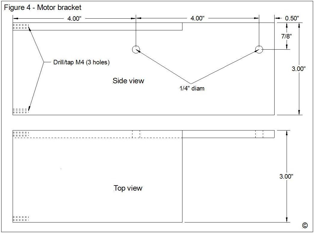
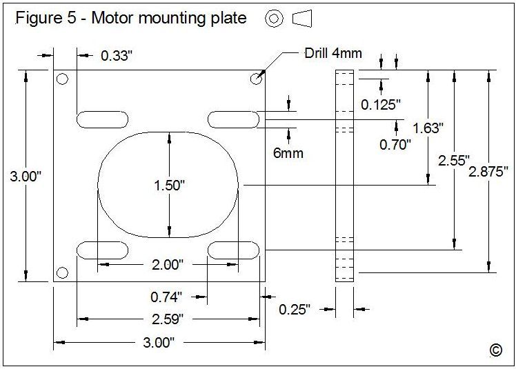
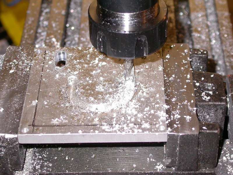
Photo 9: Machining the motor mounting plate
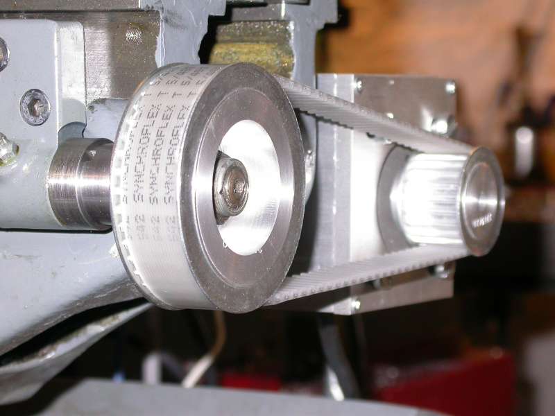
Photo 10: The drive system installed (front view)
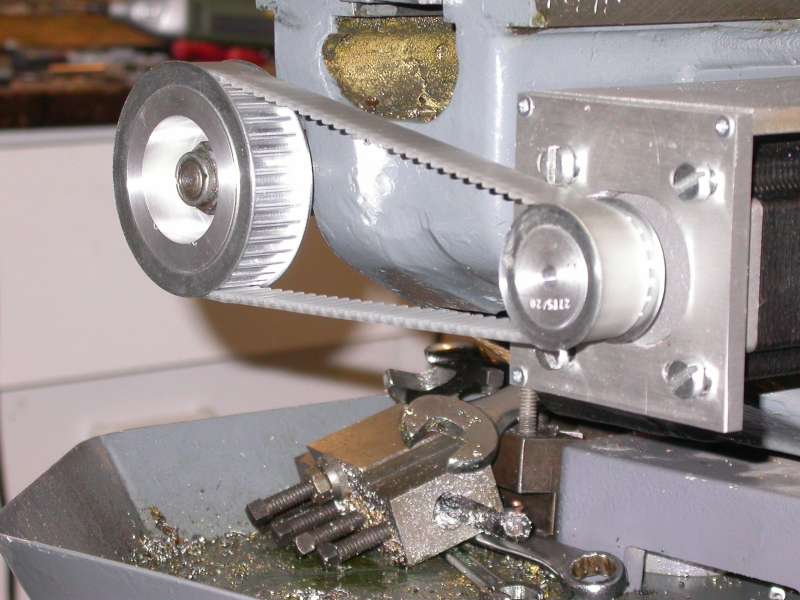
Photo 11: The drive system installed (rear view)
Testing the leadscrew drive
At this point, the leadscrew is operable under stepper motor control, and I was keen to evaluate what kind of performance I could expect when using the lathe in this form - in particular, what size of motor I would need to drive the leadscrew under real cutting loads and realistic feed-rates. Using one of my DivisionMaster controllers, and the smaller size of motor (Arc Eurotrade part number AC570764525I, 180 Ncm) I found that the fastest rate that I could drive the saddle was around 33"/minute (840mm/minute) with the standard 24 volt DivisionMaster supply. The DivisionMaster can only drive 2A/phase, whereas the motor is rated at 2.5A/phase; however, as discussed previously in my Taig Mill conversion article, it is the supply voltage that is the limiting factor on top speed with stepper drives, not the current - double the supply voltage and the . To demonstrate this, I swapped to a 48V supply, and found that the maximum feed rate was about 60"/minute (1540mm/minute), almost exactly twice the speed.
This kind of maximum speed would only ever be used only for "rapids" - repositioning between cuts - as at that speed, there would be a limited amount of torque left over to handle cutting forces, even if you were using materials and cutters that could handle that kind of federate, so 1.5 metres/minute seemed to me to be plenty good enough for the application, and in practice, probably much faster than I would really want the saddle to move. I decided to take the next step in testing the setup, and cut metal under power to see whether, at realistic cutting speeds, the motor was going to be powerful enough for the job.
With the DivisionMaster set for 750 steps/second (which gives a federate of 7"/min, or 178mm/min), facing a piece of steel bar using an indexable carbide tipped lathe tool, I found that the limiting factor was the stiffness of the machine, and not the ability of the drive system to handle the cutting forces.
My conclusion from testing with the smaller motor was that it is well able to handle the task, and that the smaller Arc Eurotrade stepper drives (3A, 40V) would also be suitable to drive the motors. I therefore saw little point in bothering to test the larger motor, especially as doing so would have necessitated boring out the motor pulley to 10mm to accommodate the motor shaft (the smaller motor has a ¼" shaft).
The other conclusion I reached was that the DivisionMaster can actually be pressed into service as an electronic finefeed and saddle stop for the lathe. In its current form, the DivisionMaster firmware is designed to perform angular moves with a rotary table or dividing head; however, you can "cheat" so that the display can be interpreted in linear dimensions. With the leadscrew drive I have described, a full revolution of the motor results in ½ a rev of the leadscrew, and a linear movement of 1/16" (the screw is 8TPI, and the pulleys give 2:1 reduction). So 16 revs of the motor will give exactly 1" of saddle movement. Hence, if you can make the DivisionMaster believe that it is dealing with a rotary table with a 5760:1 worm drive, degrees on the display would represent inches of movement. This is a larger worm ratio than the controller can handle, but setting a ratio of 576:1 works fine, and allows 10 degrees on the display to represent 1" of movement. With the controller set up this way, you can have adjustable continuous fine feeds, rapid saddle traverses, and electronic "saddle stops" for accurate cutting up to a shoulder or boring to a set depth.
Unfortunately, the numbers don't work out so nicely if you want to use Metric units, but the approach is useful nonetheless on an Imperial machine like mine. (If you had a Metric leadscrew, the problem would be reversed - it would be easy enough to set the DivisionMaster so that the display would show Metric units, but not so easy to use Imperial.) So another project gets added to my list - modifying the DivisionMaster firmware so that it properly handles linear moves, and can operate in both Metric and Imperial units. I hope to be able to report the completion of that project at some point in the future!
That completes the mechanics of the leadscrew conversion, although some may wish to enclose the pulleys and toothed belt at the tailstock end of the machine on safety grounds. In part 2, I will describe the mechanical conversion needed to drive the cross-slide feed screw, in part 3, I will describe the drive circuitry and the use of Mach 3 as a CNC control.
PARTS LIST
1
Suppliers and other contact details:
- Hemmingway Kits, 126 Dunval Road, Bridgnorth, Shropshire, WV16 4LZ, UK. Tel: 01746 767739 Website: http://www.hemingwaykits.com/
- Arc Eurotrade Ltd, 10 Archdale Street, Syston, Leicester, LE7 1NA, UK. Tel: 0116 269 5693 Website: http://www.arceurotrade.co.uk
- RS Components. Tel: 01536 201201 Website: https://uk.rs-online.com/
- DivisionMaster controllers are no longer available.