Introduction
In parts 1, 2, and 3 of this series of articles, published in MEW issues 138, 139, and XX, I described modifications to the ML-7 leadscrew and cross-slide feed screw thrust bearings, the installation of stepper motors to drive the leadscrew and cross-slide, and building the stepper motor drive electronics. In this fourth article, I will describe the final pieces of the jigsaw - configuring a PC to drive the control hardware, using Mach 3 software under Windows XP.
Choosing a PC
With the mechanical conversion and the drive circuitry all in place, all that remains before the system is functional is to configure Mach 3 on a suitable PC. I'm not planning to attempt to write a tutorial on using Mach 3 as part of this article; apart from anything else, as this is my first venture into using Mach 3, I am very far from being a Mach 3 expert, so I will leave that to others for the time being.
Mach 3 runs under Microsoft Windows; either Windows XP or Windows Vista, so the first problem is to find a suitable PC, with a parallel port, that runs XP or Vista, and that is reasonably powerful (a 2 GHz or better processor is advisable). It is also advisable to avoid PCs that have integrated shared memory" graphics functions, as these can be problematic with Mach 3, although as PC processor performance improves, this is getting to be less of an issue. The PC I bought for this exercise was a 3GHz MaxData desktop machine that came from Ebuyer, and was already loaded with Windows XP. If you can get hold of an XP machine, I would go for that rather than a Vista machine, as XP is rather more of a known quantity as far as running Mach 3 is concerned. If you can't find a PC with a parallel port, then it is still possible to add one if there is a spare slot on the PC's mother board. Some laptop computers will run Mach 3 successfully; however, particularly as laptops with parallel ports are becoming as rare as hens' teeth, I believe that you stand a better chance of getting a working system if you start with a desktop machine than a laptop.
It is preferable to start with a "pristine" machine when loading Mach 3; either a new machine or one that has had its operating system freshly reloaded. That way, you can be much more certain of getting a clean installation, and avoid any problems that may have been left around in the system by other software that had been loaded into the machine. Also, it is preferable to keep to the absolute minimum of other software on the machine you are using to run Mach 3; the last thing you want is for unforeseen interactions between Mach 3 and your other software to mess up the operation of the machine. In other words, regard the Mach 3 machine as a dedicated CNC system and nothing more; don't expect to be able to surf the web while you are cutting parts, any more than you would expect to be able to do that on a dedicated CNC machining centre from one of the big name manufacturers. In fact, it is advisable to disable any networking capability that the machine has, and rely on the use of disks or "memory stick" drives to transfer data between the Mach 3 system and any other PC that you may use for making CAD drawings, generating G-code, or downloading the latest version of Mach 3.
As mentioned in Part 3, I bought a flat screen LCD monitor from Ebuyer with the computer system; the monitor doesn't need to be particularly high spec - I simply went for the cheapest LCD monitor I could find on Ebuyer at the time. It is possible (and very desirable too) to use a touch screen with Mach 3; however, these tend to be considerably more expensive than normal LCDs. You will also need a keyboard and mouse of some description; I decided to try a compact wireless keyboard that has a built-in "joystick"-style pointing device, as shown in Photo 1. This is a slightly odd beast to use, but can be used with the keyboard held in the hands, although the keyboard is just a shade too big to type with the thumbs; however, the "mouse" buttons can be operated by the left thumb, while the joystick is operated by the right thumb. This joystick function also has other potential advantages, as I will describe later on. I haven't bothered to list part numbers for these PC components, as the availability and specification of these devices seems to change too rapidly for that to be useful; best to see what is available on the market at the time. It is also worth bearing in mind that a PC that has been outgrown by the needs of the bloated and power-hungry software packages that we seem to get foisted on us these days may still be useful as a Mach 3 machine, especially after giving it an operating system re-load.
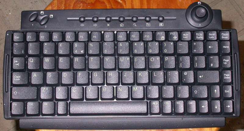
Photo 1: PC wireless keyboard with built in joystick/mouse
Installing Mach 3
I would strongly recommend that you read the Mach 3 documentation before you attempt to install or configure Mach 3 on your PC. There is a lot of useful information to be found on the Mach 3 website, including a discussion forum where you can post questions and get answers from Mach 3 experts, and several "videos" that talk you through the use of Mach 3's facilities; however, the best starting point is a document called "Using Mach 3 turn" which can be found at http://www.machsupport.com/docs/Mach3Turn_1.84.pdf. In particular, this article contains sections on installation and configuration of the software; don't try to install the software before reading it, preferably more than once, so you are clear about what is required. As this document describes the installation process in detail, I won't repeat that description here, so the rest of the article will assume that you have successfully installed Mach 3 on your machine.
The latest versions of the Mach 3 software and the various "plugins" and other software accessories can be found in the "Downloads" section of the Mach Support website. At the time of writing, the current "lockdown" version of Mach 3 is R2.63 and the current "development" version is R3.041. Mach 3 is undergoing pretty much continuous development as new features are added and bugs are fixed; the "lockdown" version is one that is supposedly stable, however, in practice, it has known bugs that have been fixed in the development version. Hence, the development version was the one that I downloaded and used.
Mach 3 does have a license fee associated with it; you can use it freely without paying the fee, but some of the more advanced features are not available unless you pay the license, and the size of the G-code program that you can run is limited. As the license fees fund the ongoing development of the software, I would encourage you to buy a license if you plan to use this software on a regular basis.
Configuring Mach 3
Mach 3 is a complex and powerful software system, and one that has considerable flexibility in the way it can be configured. On the one hand, that is a good thing, as it means that it should be possible to configure it to do pretty much whatever you need; on the other hand, it means that the process of configuring it to do exactly what you want takes time and understanding of how the system works. What I plan to do here is to describe the process of configuration that I went through to reach the point where I have a working system able to drive the hardware I have built; I don't plan to describe the full spectrum of what is possible with the Mach system, as that would take some considerable time.
Once Mach 3 is installed on your computer, you will find that a number of Mach 3-related icons will have been added to your PC's desktop, as can be seen in Photo 2; one of these is labelled "Mach3Turn". Double-clicking this icon starts the Mach 3 system, using the configuration contained in the file "Mach3Turn.xml". One of the handy features of Mach 3 is that an entire set of machine configuration parameters is documented in an XML file, so you can quickly switch between configurations by the simple expedient of re-starting Mach 3 with the appropriate XML file. A second icon on the desktop, labelled "Mach3 Loader", allows you to start Mach 3 with any of the available configurations. Double clicking the Mach3 Loader icon brings up the "session profile" window shown in Photo 2, in which you can see the available XML files on my system at present. This window also allows you to "clone" an existing configuration by copying it and assigning a different name to the copy. So, you might, for example, choose to keep a master copy of your configuration's XML file, and clone a copy for experimentation with other settings, allowing you to restore the old settings if you need to.
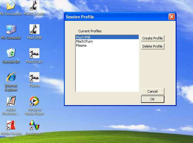
Photo 2: Session profile window
The Mach 3 installation is contained in a subdirectory of the main "C" drive, called (unsurprisingly), C:/Mach3. This is the subdirectory where the XML configuration files are stored, so if you take up my offer of a copy of my XML file, you will need to copy it into this directory, where it will overwrite any file with the name "Mach3Turn.xml", and therefore become the configuration that will be loaded when you double-click the Mach3Turn icon. If you don't want this to happen, then rename the file to something else ("TonysMach3Turn.xml" for example) before copying it into the Mach3 directory; you will then need to use the Mach3 Loader icon instead, and select the configuration to use from the list it offers you.
Whichever route you take, using the Mach3Turn icon, or Mach3 Loader and then selecting a Turn XML file, the Mach3 software will load and will present you with a screen rather like the one shown in Photo 3, with a large red Reset button flashing in the bottom left corner, a list of buttons to select different screens on the right, and a line of menu tabs along the top. For the moment, your interest is on the second menu button from the left, labelled "Config". If you click that tab, you get a drop down menu offering a list of options, as shown in Photo 4. The first four menu options form a natural succession; the first is "Select Native Units", which allows you to specify the units that you will use to define the motor performance parameters, the second is "Ports and Pins", which allows you to specify how many axes are operational, and which pins on which parallel port (there can be multiple ports) relate to which function, the third is Motor Tuning, which allows you to define the way the motors operate, how fast they can accelerate, and what their maximum speed can be, and the fourth is General Config which, as its name implies, allows a number of general configuration parameters to be set.
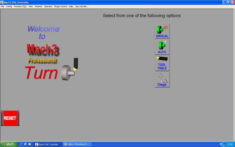
Photo 3: Initial Mach 3 screen
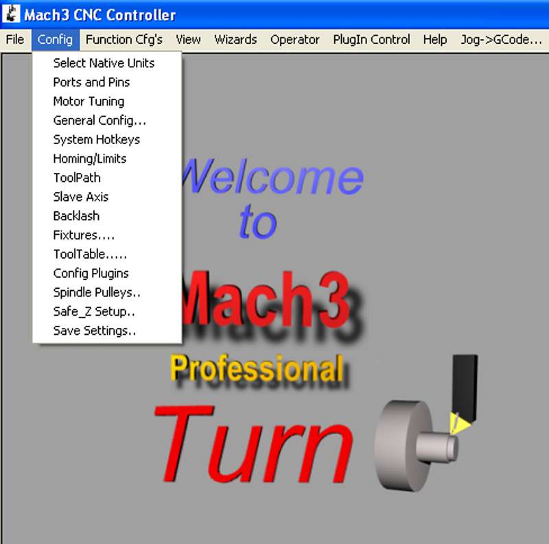
Photo 4: Config menu
Starting with Native Units, Photo 5 shows the window that opens when you select that tab; the options are to click MM's or Inches to select the appropriate units. As we are dealing with a ML7 that has Imperial leadscrews, Inches is the most convenient choice here; if you were setting up a metric machine, you would choose MM's.
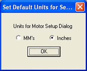
Photo 5: Select units
Ports and Pins
The Ports and Pins menu item opens a window that in turn contains seven tabbed sections, dealing with different aspects of configuring the interface between Mach 3 and the outside world, via the parallel port(s). Dealing with these tabs in succession, the first is Port Setup and Axis Selection, shown in Photo 6. If you need to use more than one parallel port, this is where you would configure the address of the port and enable it; as this project requires only a single parallel port, and it is likely to be located at the default address, it is unlikely that you will need to change its settings from the ones shown in the photo; a tick in the Port Enabled box for port 1, and the address set to 0x378. This screen also allows the "kernel speed" of the Mach 3 software to be set; again, it is unlikely for this project that you will need to change this from the setting shown of 25000Hz.
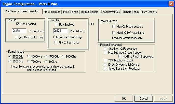
Photo 6: Port and axis setup
The next tab, Motor Outputs ( Photo 7), is where the step and direction signals for the various axes are assigned to specific output pins of the parallel ports. For this project, we are interested only in the X and Z axes, which correspond to the cross-slide and the leadscrew respectively. So in the Enabled column, there should be an "X" next to all of the axes except for the X and Z axes. Clicking in the box toggles between a "Tick" and an "X". In the second and third columns, Step Pin# and Dir Pin#, there should be 3 and 2 for the X axis, and 7 and 6 for the Z axis; all the others should be set to zero. The column marked "Dir LowActive" defines which way the motor will spin when the software wants it to go in a particular direction. This will probably need to be set to "X" for all axes; however, if you find that the X axis moves away from the work (X axis position increasing) when executing a move that should take it towards the work (X axis position decreasing), then this setting needs to be changed to a "Tick" for the X axis. Similarly, if you find that the Z axis moves away from the headstock (Z axis position increasing) when executing a move that should take it towards the headstock (Z axis position decreasing), then this setting needs to be changed to a "Tick" for the Z axis. The Step LowActive column needs to be all X's for the particular stepper drives that I used; for other stepper drives (notably the Gecko drives), this may need to be changed to active low. The Step and Dir port columns should be set to 1 for X and Z, and to zero for all other axes.
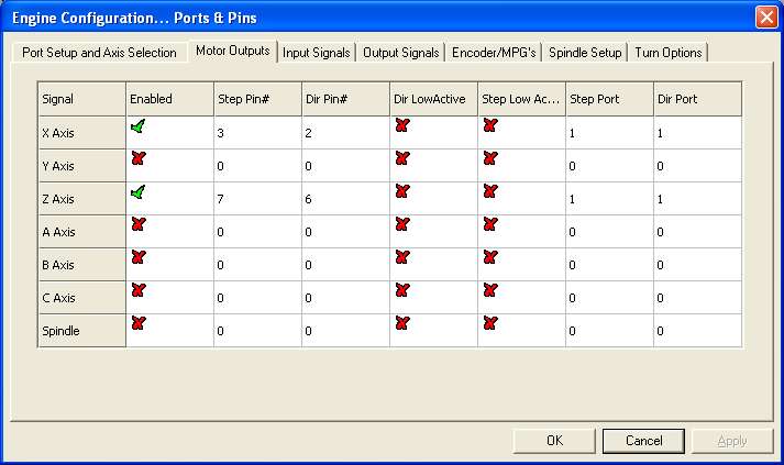
Photo 7: Motor outputs
The next tab, Input Signals (Photo 8), is where the ports and pins are defined for the two external inputs to Mach that we are using, namely, the Index (which is the name Mach 3 uses for the spindle sensor input) and the E-Stop. There are a good number of possible inputs, all of which should be disabled (a "X" in the Enabled column) except for Index and EStop; the scroll bar at the far right of the window allows you to look at the whole of the list. For the Index row, the Port and Pin columns should be set to 1 and 10 respectively, as the "In1" signal on the Optoport board is connected to Pin 10 of the parallel port. Similarly, the EStop row should contain 1 and 11 in the Port and Pin columns. The "Index" input should be set to Active Low (a "Tick" in the Active Low column); the E-Stop is set to Active High. The Emulated column should be all X's. In passing, the Emulated and Hotkey columns allow inputs to be simulated from the keyboard instead of the parallel port inputs, which could be useful for some purposes.
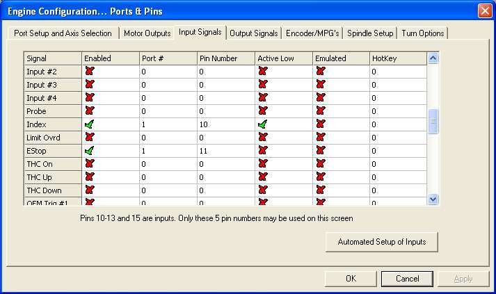
Photo 8: Input signals
Next tab is for the Output Settings (Photo 9). For present purposes, the only output that is relevant is the Charge Pump; the Optoport board requires this to be fed to Pin 1, so the Enabled column is ticked for the Charge Pump row, and the Port and Pin are both set to 1. In Photo 1 you will notice that I have also enabled Output #1 and Output #2; these I have set to pins 17 and 16, which are the pins on the Optoport board that control the two relays. In reality, if these relays are not being used (which they aren't in my system), then it doesn't much matter whether they are enabled or not.
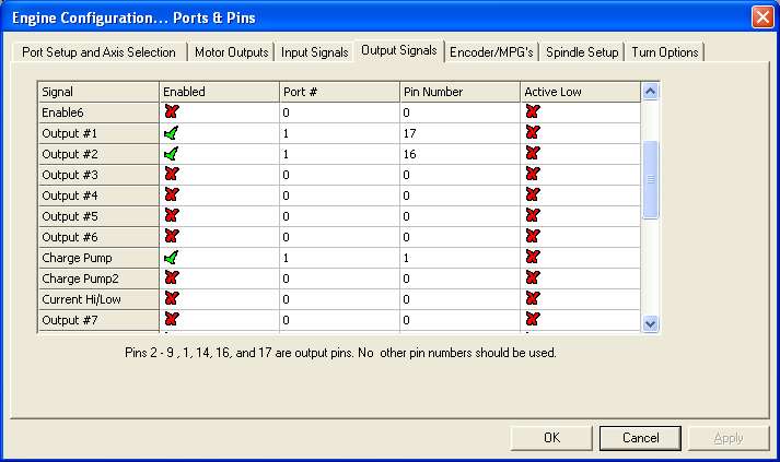
Photo 9: Output signals
The next tab, Encoder/MPG's, would be of interest if we were using encoder or MPG (Manual Pulse Generator) inputs, for example, to implement an electronic handwheel; as we are not, this tab can be ignored. The next tab of interest is Spindle Setup (Photo 10). Here, the bit that is important to us is the Special Functions box in the top right-hand corner; these define how the Index signal from the spindle sensor will be used. The three check boxes, Use Spindle Feedback in Sync Modes, Closed Loop Spindle Control, and Spindle Speed Averaging, should all be checked, and the P, I, and D parameters set to 0.62, 0.22, and 0.15 respectively; however, I suspect that some/all of these parameters are only relevant if you are using Mach 3 to control the spindle speed.
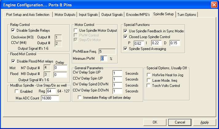
Photo 10: Spindle setup
The final tab in this set is Turn Options (Photo 11). Here, the Diameter box should be checked; this means that X dimensions are shown in terms of the diameter of the work, rather than the radius, which makes life simpler when thinking about finished dimensions, and when setting the work origin. The Reversed Arcs in Front Toolpost box should also be checked.
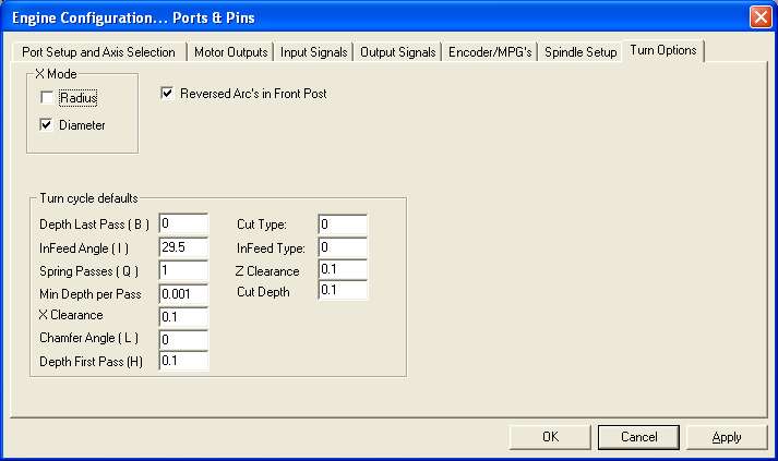
Photo 11: Turn options
Having entered all the Ports & Pins information, the "Apply" button is clicked, and the "OK" button clicked to close the window.
Motor settings
Selecting the Motor Tuning menu item brings up a window that allows the various axis motors to be configured. Photo 12 shows this window; at the right hand side, a column of buttons shows which axes are configurable - logically, you can only configure those axes that you enabled in the Ports & Pins configuration windows, so only the X and Z buttons are functional in this case. Photo 12 shows the X axis parameters. The X axis feed screw is 10 turns per inch, the stepper motor drive is set to 8 microsteps per full step, the motor does 200 full steps per rev, and the toothed pulleys give a 2:1 reduction. Multiplying these numbers all together, the conclusion is that the X axis needs 32000 steps per inch; as we are working in inch units (Photo 5), 32000 goes in the "Steps Per" box. I chose to set the Velocity and Acceleration to 30 inches per minute and 30 inches per second squared; it is certainly possible to squeeze more performance out of the X axis, but there isn't much point in doing so. Settings of 5uS for the step and dir pulse durations seemed to work OK. Click the "save axis settings" button before clicking the Z Axis button to do the same for the Z axis; this time, as the leadscrew pitch is 8 TPI, the "Steps per" figure is 25600, and the other parameters are the same as for the X axis. Again, click "Save Axis Settings" before clicking OK to exit the window.

Photo 12: Motor tuning - X
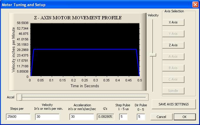
Photo 13: Motor tuning - Z
The final bit of configuration, at least for the moment, is General Config (Photo 14). In this screen, there are two parameters that affect the way that the spindle index pulse is handled by Mach 3; these are in the box at the top right of the window, marked Input Signal Debouncing/Noise rejection. The Debounce interval should be set to 0, and the Index Debounce set to 200.
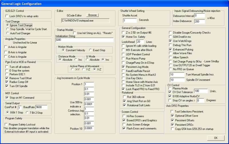
Photo 14: General config
Having completed the configuration, it is important to make sure that the parameters are saved in the XML file; to do this, select the last option in the Config drop down menu - Save Settings.
Checking things out
At this point, the main functions of Mach 3 should be properly configured. If you select the Manual button on the main Mach 3 screen, the display changes to something like Photo 15. The big red "RESET" button in the bottom left corner will be flashing; you won't be able to do anything with the system until you click on the reset button.
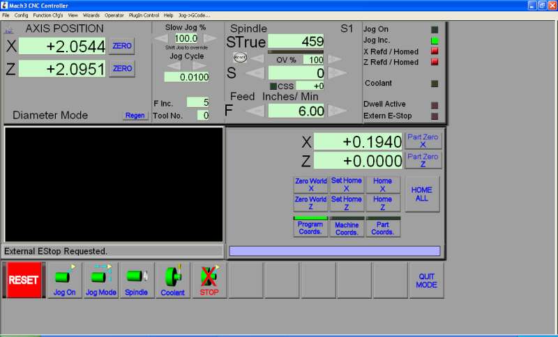
Photo 15: Manual screen
If this fails to stop the button flashing, then your E-Stop input is preventing the reset; there could be a number of reasons why this is happening, including:
- Power supply problems (check that there is around 38V on the power supply capacitor, and check that there is 5V being generated at the Optoport board's 5V terminal);
- Charge pump not operating correctly (the orange "CP" LED on the Optoport board should be lit). This could be due to misconfiguration of the outputs;
- The inputs are not properly configured in Mach 3;
- The E-Stop contacts are not closed;
- The E-Stop wiring between the contacts and the Optoport board is incorrect;
- You haven't powered the drive system on, so no signal is reaching the PC from the Optoport board;
- The USB and D25 cables between the PC and the Optoport board are not connected.
Once you manage to clear the flashing RESET button, it should be possible to "jog" the X and Z axes using the cursor keys on the PC keyboard; the up arrow key should move the cross-slide in towards the work (away from the operator), and the X Axis Position DRO (digital read-out) on the screen should decrease as the axis moves. The down arrow key should give the reverse X movements. The right and left arrow keys should work in a similar manner for the Z axis; right arrow moves the saddle to the right and the Z Axis Position DRO on the screen should increase. If either axis moves in the opposite direction to te description above, then the "Dir Low Active" setting in Motor Outputs is wrong for that axis, as mentioned earlier, and this should be changed before proceeding.
If a motor fails to move at all, then there could be a number of possible reasons:
- Power supply and Charge Pump problems (see above);
- Incorrect configuration in the Motor Outputs screen;
- Incorrect wiring between the Optoport board and the stepper drives;
- Incorrect setting of the switches on the stepper drives;
- Incorrect wiring between the stepper drives and the power supply;
- Incorrect wiring between the stepper drives and the stepper motors. If the latter is the problem, then there is also the possibility that the faulty wiring has blown the output of the stepper drive, and that you will need to replace it.
The other thing that is worth checking is that the spindle "index" sensor signal is being correctly interpreted by Mach 3. Start the lathe and look at the "STrue" DRO on the screen; if the sensor is operating correctly, then the DRO should stabilize to the true RPM of the spindle. If the value doesn't change from zero, then there could be a number of problems:
- Power supply and Charge Pump problems (see above);
- The sensor isn't operating correctly. There should be 5V on pin 1, and pin 2 should alternate between 0V and 5V as the magnet rotates past it. If this isn't happening then it could be that the sensor is incorrectly wired, or the magnet is the wrong way around (S facing the sensor);
- The sensor is wired into the wrong input on the Optoport board;
- The "Index" settings in Input Signals are incorrect;
- The "Debounce" settings in General Config are incorrect.
Hopefully, all is well at this point, you can happily "jog" the axes back and forth with the cursor keys, and the spindle RPM is displayed correctly; if not, take the necessary remedial action and try again.
Pendant control
There is just one further addition that will make using the lathe easier, and that is to add a "pendant" control. The cheapest and simplest way to achieve this is to fit a Shuttle Xpress device; this is a device that was designed to make video editing and similar tasks easier on a PC, but it lends itself well to CNC.
Two versions are shown in Photo 16; the one on the right is the standard version, and the one on the left, while mechanically and electrically identical, has been personalized by Tormach for use with their milling systems. The device has an inner wheel that rotates indefinitely in either direction; it has a click detent, and in operation as a pendant, a single click of the inner wheel causes Mach 3 to drive the currently selected axis by whatever the current jog increment is. Clockwise "clicks" cause the axis position to increase; anticlockwise "clicks" cause the axis position to decrease.
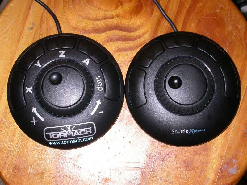
Photo 16: Shuttle Xpress versions
The outer ring is spring loaded to a central position, but can be wound anticlockwise or clockwise by a quarter of a turn or so in either direction. This ring gives progressive velocity control of the current axis; a small clockwise twist of the ring causes the axis to move slowly in the + direction, and if the twist is increased, the axis accelerates to a faster speed. Similarly, turn it anticlockwise and the axis will go the other way.
There are 5 buttons that can be configured for a bewildering array of functions; the Tormach device is clearly marked with the intent that the first 4 buttons (counting from the left and going clockwise) are used for axis selection, and the fifth button selects the jog increment size; however, on a lathe with 2 axes, the choices would be different. I chose to set the first 2 buttons to select X and Z, the third and fourth to give rapid + and - axis moves, and the fifth to change the jog increment. There is also a Shuttle Pro that has many more buttons; however, I felt that this would offer more confusion than clarity, so opted for the Xpress version.
In use, this device makes for quick and easy positioning of the axes, and the "velocity" control with the outer ring is great for quick-and-dirty manual operation of the lathe - the slowest speed gives a very fine feed. The easiest way to reference the work before you start a CNC machining operation is to face off the end of the work to give you the Z=0 position, then take a skim cut and measure the diameter to give the X diameter (this is why it is worth choosing "Diameter" in Turn Options); doing this with the Shuttle control is very quick and convenient.
Shuttle Xpress setup
To get the Shuttle Xpress working, you first need to load the Mach 3 "plugin". This can be downloaded from the Downloads area of the Mach support website; scroll down until you find the "ShuttlePRO" section (the same plugin works for all versions of the Shuttle). On your Mach 3 system, with Mach running, place the plugin file in any convenient directory and double click on it; the file will then be automatically renamed as a DLL and placed in the C:/Mach3/Plugins directory. Exit Mach 3 and restart it to ensure that the plugin is properly recognized by Mach 3, and then plug the Shuttle into a convenient USB socket.
The plugin needs to be configured; select Config, then Config Plugins from the drop-down menu, and a window appears as in Photo 17. Make sure that the Enabled box next to the Shuttle Pro entry is ticked, and then click the CONFIG button next to the entry, which will bring up the shuttle configuration screen as in Photo 18. This is laid out to look like the Shuttle Pro; for the Xpress, only the buttons in the second arc from the top are functional. As can be seen in the photo, these are set to make the first two buttons select X and Z axes, the third and fourth give rapid + and - moves, and the fifth cycles the jog increments. In the bottom right hand corner, you must make sure that the right radio button is checked to select Express or Pro, depending on which one you choose. Click "OK", and the shuttle should then be operational. I attached a disc magnet to the back of mine so that I can hang it on the front of the lathe cabinet when it is not in use.
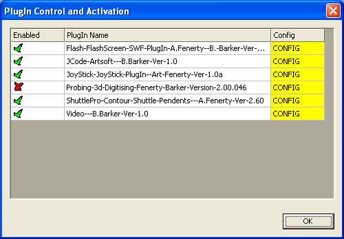
Photo 17: Configuring the shuttle plugin
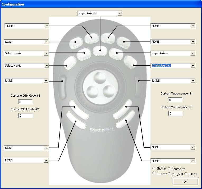
Photo 18: Shuttle button assignments
An alternative hand control device is a joystick; as I mentioned earlier, the keyboard that I chose to use has a mini joystick built in, and it can operate either as a joystick or a mouse. If you want to experiment with this, there is yet another plugin for that, which needs to be loaded and enabled in a similar manner to the Shuttle. In use, the joystick gives progressive velocity control of the axis movements, rather like the outer ring of the shuttle; however, one interesting difference is that if you move the joystick diagonally, both axes move, which can be useful.
Using the lathe
I don't plan to say a great deal about this, principally as it is very early days for me, so I am not in a very different position from anyone else coming at Mach 3 for the first time and trying to make sense of it. The best advice I can give here is to make full use of the documentation and videos that are available on the Mach support website to help you to get familiar with the operation of the system.
However, I will offer a little taster of what it can do, by way of a couple of my first two attempts at using the "Wizards"; there are two sets of lathe wizards, one for simple threading, and the other for turning. Photo 19 shows the wide range of simple turning operations, internal and external, that can be performed using the turning wizards. The first example, shown in Photo 20, was cut in three stages. First, I used the Shuttle to face off the end of the hex bar, and to turn off the flats. Having "referenced" the part by using the facing cut to set Z to zero, and the finished diameter to set the X position DRO, I used the OD Fillet wizard to plain turn to a shoulder, with a small radiused fillet in the corner. I then used the OD Taper to put on a 45 degree point at the end. For the taper cut, I was a bit to aggressive with the cutting depth and speed, so it isn't as neat as it could be, but it illustrates the "point". The wizards present you with a simple screen with boxes for the desired starting and ending positions of the axes, radiuses, angles, etc.; you literally fill in the boxes, then the wizard generates the corresponding "G"-code to cut the part and posts the "G" code in the "Auto" screen in Mach 3. If you wish to do so, you can save these "G" -code programs for later use if the operation is one that will be repeated, and you can even combine fragments of code from successive wizards to make more complex programs.
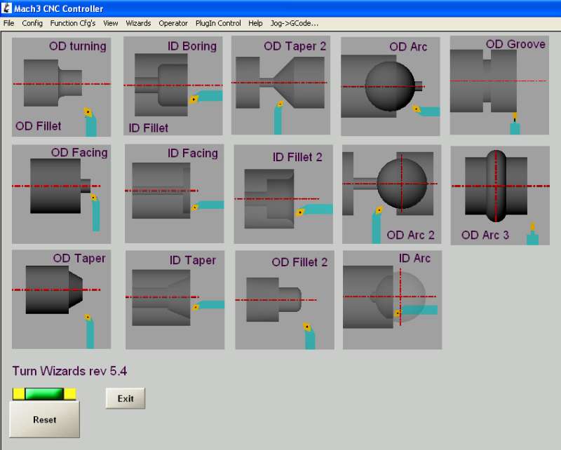
Photo 19: Wizards screen
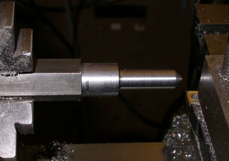
Photo 20: Plain and taper turning
The second example is a threading wizard example; the finished article (a length of 3/8" X 20 TPI thread) can be seen in Photo 21, and the corresponding Wizard screen that generated is shown in Photo 22. The wizard will tell you whether, at the chosen spindle speed (500 RPM in this case) and the chosen screw pitch (20 TPI in this case), the speed required of the Z axis is above the maximum speed that the control can achieve, and ask you to reduce the speed if need be. 500 RPM proved to be OK, so I ran the G-code generated by the wizard, as shown on the screen in Photo 23. As I haven't set up the system to directly control spindle speed (although this is a definite possibility for a future enhancement), I had to adjust the speed manually to near enough 500 RPM, using the displayed value in the "STrue" DRO, before running the program. The resultant thread wasn't as clean as I would have liked, partly because I used a rather deep cut on each pass, and partly because the threading tool wasn't the sharpest it could have been; however, the example again demonstrates the potential of the system.
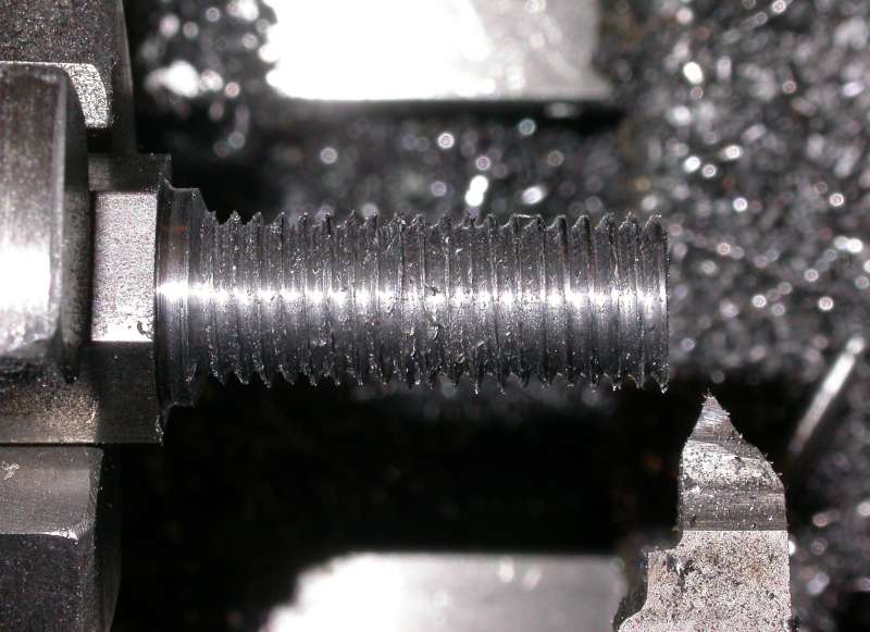
Photo 21: Threading
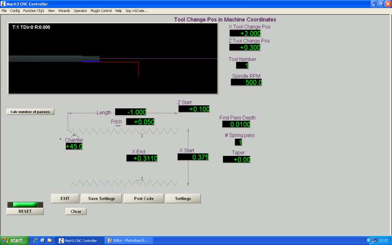
Photo 22: Threading wizard
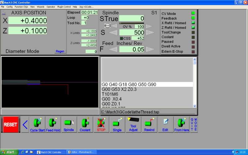
Photo 23: Run time screen
Mach 3 forums
As I have already mentioned, there is a lot of useful material to be found on the Mach Support website; there is also an online technical forum that is part of the website, where Mach users can post questions, offer advice, and so on. There is also a Yahoo discussion group dedicated to Mach issues. The people that are responsible for ongoing development of the Mach 3 software and related products are members of these forums, as are many knowledgeable users of the Mach system; if this article fails to answer any questions you have about Mach 3 (and I'm sure it will!), then these for a make an excellent starting point. You will find that the inhabitants of these for a are friendly and helpful.
A potential short cut
Configuring Mach 3 is a fairly straightforward but time consuming process, especially if you are doing it for the first time, so some may decide, after reading this article, that a short-cut is in order. It is possible to buy pre-configured Mach 3 systems - the so-called "MACH-in-a-box" - from Lester Caine's Model Engineers Digital Workshop. This is a boxed PC system, with Mach 3 pre-loaded and configured, ready to run. To date, I believe Lester has been aiming these systems at milling machine installations; however, I will let him have a copy of the XML configuration file I have used in this project so that he can supply pre-configured systems set up with the appropriate parameters for the hardware configuration I have described here. As mentioned at the end of Part 3, I will also email copies of the XML file to anyone that wants it; email me on tony @ jeffree.co.uk if you want a copy. Even if you plan to install the software yourself and tinker with the configuration parameters, starting off from a "known" configuration can be very helpful.
While I am happy to answer email questions about this series of articles as best I can, please bear in mind that I am still very much a novice as far as Mach 3 is concerned, and I am certainly not the best source for advice on the finer points of Mach 3 configuration or operation, so please be prepared for answers of the form "I don't know - try the Mach 3 forums".
Closing words
There are only two things I regret about choosing to use Mach 3 for this project; the first is that I didn't start using Mach 3 sooner, and the second is that it now means I will want to go back to my two previous mill conversions and upgrade them to use Mach 3 as well. It isn't as easy a system to get to grips with as DeskCNC; however, it is far more flexible in the ways it can be used, has good support for lathe operation, and even without the addition of a "proper" CAM front-end, such as Dolphin Partmaster or Vectric's Cut2D or VCarve, the in-built wizards offer most of what you need for run-of-the-mill (or should it be run-of-the-lathe?) CNC turning operations. The combination of the Mach 3 capability and the Shuttle Pro for manual override makes the machine very usable, and the fact that you can turn off the hardware and still use the lathe as a manual machine is great for those occasions when what you are doing just doesn't need the sophistication of CNC control.
Finally, I'd like to say a thank-you to John Stevenson for the advice he has provided over the course of this project (and yes John, I have lost count of how many beers I owe you!). He convinced me that Mach 3 was the only way to go for a lathe conversion, and discussing various aspects of the conversion with him has been very helpful in clarifying how best to do the job.
Suppliers and other contact details:
- The MACH support website: http://www.machsupport.com
- Ebuyer's website: http://www.ebuyer.com/
- Contour Design for Shuttle Xpress: http://www.contourdesign.com/shuttlepro/shuttlexpress.htm
- Tormach's website: http://www.tormach.com/
- DivisionMaster controllers, RevMaster sensor boards, and "MACH-in-a-box" systems are no longer available.
- Yahoo discussion group for Mach users: http://groups.yahoo.com/group/mach1mach2cnc/
- Vectric CAM software is available from Vectric Ltd, Unit 3 Dunstall Court, Astwood Lane, Feckenham, Worcesteshire, B96 6QH, United Kingdom, Tel: 01527 460 459. Website: http://www.vectric.com/
- Dolphin Partmaster software is available from Dolphin CadCam Ltd., 7 South Dean Road, Kilmarnock, KA3 7RE Tel: 01563 543989 Website: http://www.dolphin-systems.co.uk/