A CNC Headstock Dividing Attachment for the ML7
Tony Jeffree
Introduction
A good many people have built ML7 and Super 7 headstock dividing attachments over the years, using the designs originally devised by Peter Radford, and later described by G.H. Thomas in his book "Dividing and Graduating" (no longer in print), later re-published as part of "Workshop Techniques"[1]. As I own an ML7, I have planned for some while to build one of these attachments, but to convert it for CNC use in conjunction with the DivisionMaster[2] automatic indexer. The primary motivation was firstly to demonstrate that "it could be done", and secondly to be able to feed back the right information to various people that have asked me for advice on how to adapt their dividing attachments in this way.
As George Thomas points out, the ML7 is not ideally suited to performing division operations, as its bull-wheel has 65 teeth, which is far from ideal as you need a large number of non-standard hole-circles in your dividing plates to get all of the useful divisions. George Thomas's solution was to use his micro-indexing attachment in order to generate unusual hole circles; however, for those that find using a conventional dividing head to be problematic, keeping track of movements on the indexing arm and the micrometer thimble at the same time would be something of a nightmare. Of course, replacing the manual dividing components with a stepper motor and an automatic indexing device such as the DivisionMaster controller makes all of these problems go away; the boring, and all too often, error-prone, job of keeping track of the angle to be moved can be given to the controller, while the operator concentrates on the machining.
The general plan, then, was to build one of these dividing attachments from the excellent Hemmingway[3] kit, discarding any bits that related to manual indexing, and replacing the indexing arm/dividing plates with a suitable stepper motor. So, I bought the kit for the ML7 version of the attachment (there is a different kit for the Super 7 and its variants, as the pitch of the bull-wheel is different on these two machines), and proceeded to allow it to gather dust, in the traditional manner, for three or four years, in a quiet corner of the workshop.
As an aside, I'm convinced that there is a process of "maturation" associated with any new project - possibly somewhat related to the process of "ageing" and "weathering" that improves the quality of iron castings - anyhow, it is clear that this particular kit needed to gather a considerable layer of dust before it was properly matured and ready to be built. Finding myself with some unaccustomed spare time after the New Year celebrations had died down, I decided to excavate the corner of the workbench where the kit had been "maturing", and think through the modifications that would be necessary to CNC-ize it.
This article concentrates on the changes that need to be made to the basic design of the dividing attachment to convert it to stepper drive, and doesn't give a blow-by-blow account of constructing the parts of the attachment (such as the mounting bracket that fits on the countershaft bracket of the lathe) that are unaffected by the change to motor drive. For details of those aspects of the construction, I refer the reader to the excellent material in George Thomas's book and to the instructions provided with the Hemmingway kit.
The approach taken here is appropriate for those that are building the dividing attachment from scratch and have no intention of ever using it in conjunction with the manual dividing attachments described by G.H. Thomas; if you wish to modify an existing dividing attachment, retaining the ability to use the manual option, then you will have to adopt a different approach, maybe devising a way of mounting a stepper motor in place of the division plate/indexing arm, but this shouldn't be terribly hard to do. Similarly, the approach adopted here could be adapted to build bull-wheel dividing attachments for use with other lathes.
In writing up this project, I have made some changes to the dimensions that I used in the prototype, in the light of experience during its construction; hence, the eagle-eyed amongst you will notice that the photos differ from the drawings in a number of minor respects. Hopefully, the version that appears in the drawings will be an improvement over the prototype!
The modifications
The component parts of the kit consisted of several lengths of round and rectangular bar stock of assorted dimensions, three iron castings for the bearing blocks, and a partially machined worm of the right pitch to properly engage the teeth of the bull wheel. After studying the drawings and associated description for some while, I dug out my copy of "Dividing and Graduating" for further illumination. The drawings supplied with the kit seemed to show only the major differences between the ML7 design and the Super 7 design, so the full text in George Thomas's "Workshop Techniques" was extremely helpful in understanding how it was all supposed to fit together.
The original dividing attachment uses plain bearings. There are two identical bearing blocks either side of the worm, and a further bearing block at the operator end of the worm shaft that serves a couple of purposes; it forms the end thrust bearing that prevents axial movement of the worm shaft, and is also used to mount the various dividing components (dividing plate, micrometer attachment, and so on). This latter bearing block didn't really serve any purpose in my CNC version, so I discarded it, and decided to control end float by other means.
Plain bearings are a source of relatively high friction, which is undesirable in a stepper motor driven device, so I decided that I would use ball races either end of the worm shaft instead. I had a few of ¾" OD, ¼" ID ball races to hand that looked like they would fit in reasonably well size wise; obviously, close Metric equivalents - for example 19mm OD, 7mm ID - could be substituted with suitable dimensional changes to the bearing blocks and worm shaft. You could go up to 22mm OD without too much difficulty.
The remaining two cast bearing blocks looked to me to be potentially a pain to machine; it has always seemed to me that using cast components can be a false economy (in terms of machining time) unless the shape is complex – with simple shapes like these, you spend more time “truing up” the sides of the casting, and deciding how to get a firm hold of its sloping sides while you do it, than you would have done making the part from bar stock to start with, especially if (like me) you have a metal cutting band saw to hand. So, these two cast components joined the other one in the scrap box, to be replaced by bearing blocks cut from ¾" X 1" bar stock.
Bearing blocks
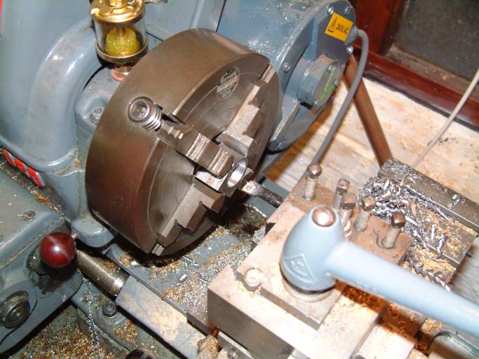
The design of the bearing blocks can be seen in Figure 1. These are simple to construct; the blocks are cut to finished size (1.125" long), and bored in the 4-jaw chuck so that the ½" through hole is exactly 5/8" from one end and central in the 1" width of the block (see Photo 1). The counterbore that forms the seat for the ball race is then machined; the objective here is for a close, but not press, fit. There are two tapped holes in the base of each bearing block to mount the blocks on the main bearing bar of the dividing attachment; in my case, I used UNF 10-32 screws as these were in plentiful supply in my screw box, but substitution of any appropriately similar size (2BA, M5, 3/16 BSF - whatever) is clearly an option.
Once the housings have been fully machined and finished, the bearings can be permanently fitted in their seats with the help of a drop of your favourite bearing retainer (Superglue works just fine for this), taking care not to use so much that the bearing itself gets a wetting, as there is no alternative at that point but to chuck the bearing in the bin and use another one (just don't ask how I know, OK?).
Main bearing bar
The bearing blocks are mounted on the main bearing bar of the dividing attachment, a length of 1" X ½" steel bar stock; see Figure 1 for dimensions. The counterbored holes for mounting the bearing blocks, and the single counterbored hole that attaches the far end of the main bearing bar to the square section cross-member, are machined to suit the socket head screws that are to be used. I had the advantage of being able to use my CNC mill to spot the positions of these holes (and also the matching holes in the bearing blocks), thus ensuring an accurate fit. Once the main bearing bar has been attached to the cross-member, at 93.9 degrees to allow for the helix angle of the worm, the end of the bar can be filed or ground off to make the end flush with the cross-member.
Worm shaft
The next job is to machine the worm shaft. The dimensions are shown in Figure 3; this is a fairly simple operation, but should be performed with due attention to maintaining concentricity between the worm and the machined portions of the shaft. One end of the part-machined shaft had a centre machined in it; I used a fixed steady and a 4-jaw chuck to drill an accurate centre in the other end, and then machined the shaft between centres to the dimensions shown. The objective is for the extreme ends of the shaft to be a close fit in the ID of the bearings chosen for the job. The short end of the shaft (the right hand end as seen in Figure 2) is drilled and tapped to take a cap head screw; this, along with a ½" diameter setscrew collar (this can be machined to suit from a scrap of ½" round bar) at the other end of the shaft, will provide the means of adjusting the pre-load on the bearings and thus eliminating any end-float in the worm shaft.
At this point, a trial assembly of the worm shaft and bearing blocks will allow the overall arrangement to be checked. The set screw collar should be positioned so that the short end of the shaft doesn't quite protrude through the far end bearing, allowing a cap head UNF 10-32 (or equivalent) screw and washer to be screwed into the far end of the shaft t adjust the preload. On final assembly, this screw will be retained with your favourite thread-locking compound, but best to leave it dry at this stage.
Motor mount
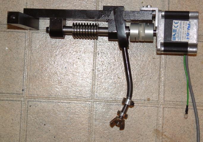
Next, machine the motor mounting plate shown in Figure 3. Mine was made from a piece of 1/8" X 1" X 1" aluminium angle, but pretty much anything (brass, steel, whatever) will work for this. The mount is designed to accept a NEMA 23 frame size stepper motor; to do a reasonable job of driving the Myford headstock, this motor should be rated for a holding torque of 140 oz-in (approx. 1 Newton-Metre) or more. The motor is coupled to the end of the worm shaft by means of an Oldham coupling, as can be seen in Photo 2. These can be obtained from Electromail/RS Components[4]; two hubs are required, part number 748-055, and the plastic torque disc is part number 319-590, for a coupling that will take ¼" shafts. Other hubs are available with different bore sizes if necessary. Unfortunately, the torque discs are only sold in multiples of 10. Alternatively, DivisionMaster Ltd can supply these couplers in single units.
The motor has a circular register, 1.5" in diameter, which matches the corresponding cut-out in the motor mounting plate. The final position of the two holes for mounting the motor, and the two holes for attaching the motor mounting plate to the main bearing bar, should be determined by trial assembly – the motor shaft and the worm shaft should be as close as possible to being on the same axis. The Oldham coupling will tolerate a considerable degree of misalignment, but the more misalignment there is, the higher the frictional load on the motor, and the less torque is available to drive the lathe spindle. There should also be sufficient space between the ends of the two shafts to accommodate the torque disc of the coupling without its free movement being restricted by contact with the ends of the shafts.
Swinging latch and clamping plate
The swinging latch that holds the worm in engagement with the bull wheel is constructed pretty much as described in George Thomas's original design, and is pivoted at the same distance from the far end of the main bearing bar as in the original design. The square clamping plate, cut from ¼" X 1" steel bar, is positioned slightly differently; however, the positioning/clamping of this plate is far from critical, as its purpose is simply to locate the swinging latch at the right position along the main bearing bar. Having marked this pivot position, I clamped the clamping plate in position, and drilled both the clamping plate and the main bearing bar for the clamping screw hole using the appropriate tapping drill, then opened up the clamping plate hole and counter-bored it to clear the screw and its head (M4 cap head screw in this case). With the clamping plate in position, the pivot hole can be drilled across the width of the assembly.
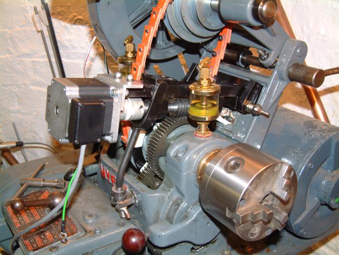
The only deviation from the original design as far as the latch itself was concerned was that I chose to tap the thread M8 and used a wing nut that I had to hand, rather than machining up a special nut for the purpose. I found that, as I have a gearbox fitted to the lathe, I had to shorten the latch arm somewhat to make it fit properly, and also had to locate the latching post rather higher on the headstock casting than specified - around the centre of the raised "D" of "Myford". In order to get a flat surface, I ground away the raised letter "D", so I am now the owner of a Myfor lathe - see Photo 3.
Assembly and adjustment
The final assembly involves careful adjustment of the setscrew collar and the screw in the far end of the worm shaft to minimize any end-float in the shaft, while at the same time, not applying so much pre-load that the bearings no longer run smoothly. A trial run is advisable before applying a drop of your favourite thread locking compound and adjusting the screw to its final setting.
One of the Oldham hubs is slid into place on the end of the worm shaft, and one onto the motor shaft, before mounting the motor in position; it should be possible to insert the torque disc between the two hubs, and then slide the hubs back to engage with the disc, before tightening the clamping screws on the hubs. The hubs I used were of the split clamp variety; others are available that use a pair of set screws at 90 degrees to each other, but the split clamp hubs are easier to use and avoid marring the shafts and thereby generating disassembly problems.
The attachment is attached to the lathe in the same way as the original design - two conical pivots engage with the cross member attached to the end of the main bearing bar (see Photo 4), and the screws on the swinging latch are adjusted to minimize backlash between the worm and the bull wheel. I found that there was a minimal amount of backlash that simply could not be adjusted out - this I put down to the worm having been cut with a slightly too wide form tool, or possibly, it may be a reflection of wear in the bull wheel itself. It might have been useful to adjust the angle of the worm relative to the gear to remove this play altogether, but in practice, I doubt that this will be a big issue. If need be, a loop of cord round the chuck and a weight on the end will ensure that the backlash is always taken up in the same direction.
Final words
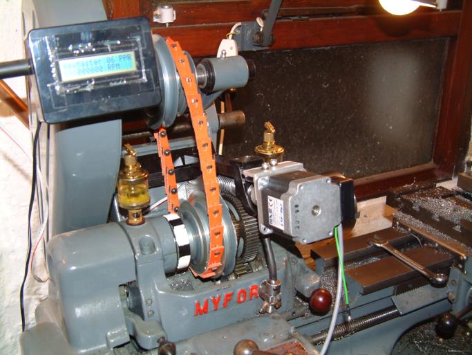
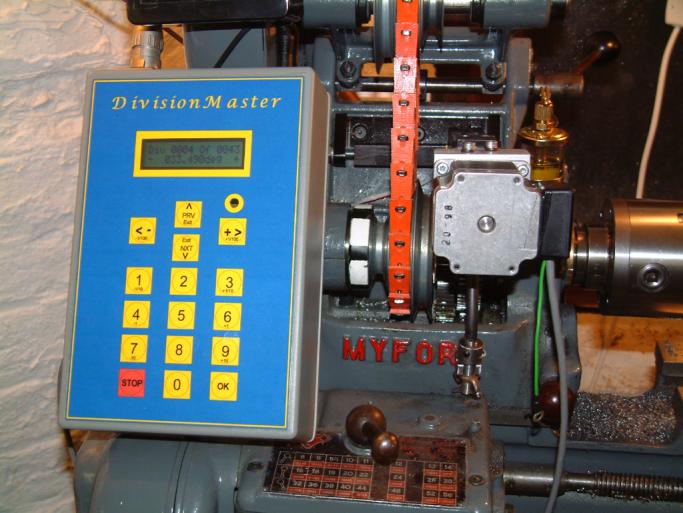
The final shot in Photo 5 shows the motor connected to a DivisionMaster controller, set for 43 divisions, not the easiest division to set up on a conventional dividing head, let alone a dividing head that has a 65:1 worm drive! The ease of fitting/removing this dividing attachment, coupled with the convenience of being able to dial in appropriate angles or numbers of divisions on the DivisionMaster controller, make this approach to dividing operations in the lathe extremely convenient.
A 140 oz-in motor seems to give ample torque to drive this setup on my lathe; however, as the torque needed will depend on how "free" the headstock bearings are, it may be necessary to vary the motor torque accordingly. Needless to say, when the dividing attachment is fitted, the lathe drive belts should not be tensioned, otherwise the dividing attachment will be attempting to drive the lathe's countershaft and spindle motor as well as the headstock spindle.