Introduction
Many of the new machines that are being imported from the Far East come fitted with variable speed drives, and owners are converting old machines fitted with three phase motors to use variable speed 3-phase "VFD" drive systems. These machines give us the ability to infinitely vary the spindle speed without the need to change belts. With some such systems, and my Taig mill with its variable speed spindle drive borrowed from a Sherline mill is a good example, the range of useful speeds obtained with a single pulley position is such that it is rarely necessary to change the belt over to a different set of pulleys even if different speed ranges are available. I have my Taig almost permanently set on the 3rd from slowest of 6 speed ranges, which gives me a useful range of dead slow to 5,000 RPM; I have tried it on its fastest pulley combination, which gives in excess of 15,000 RPM with the Sherline motor, but only to demonstrate how fast it will go as the headstock bearings would probably not stand such abuse for long.
With most of these systems the common factor is that, although you can adjust the spindle speed, you no longer have any clear idea of what the actual spindle speed is at any point in time. Hence this project; a simple tachometer or rev counter that can be readily fitted to a wide range of different machines, and will give a useful range of RPM measurement. An article that I wrote on spindle and surface speed measurement for issue 60 of MEW introduced some techniques for measuring spindle speed with the aid of a digital multimeter with a frequency scale; this project makes use of some of the sensing techniques discussed in that article, but describes a dedicated tachometer unit with its own LCD display.
The description that follows should give sufficient information for anyone that has reasonable soldering skills to construct a finished unit entirely from scratch, including etching a board if necessary; however, as the circuit is constructed around a PIC 16F84 single-chip microcomputer, anyone wanting to do the whole job themselves would need access to a PIC development system in order to develop the firmware and program the chip.
For those constructors that are able to make sense of a "C" program or have the ability to programme PIC chips using standard HEX files, the "C" and HEX files are available on this page.
Before getting into the detail of the rev counter itself, I have included a bit of background information on these PIC devices, and some of the development tools that are available (at very reasonable prices) for them. These early sections are probably only of interest to people that feel comfortable enough with electronics and programming to "have a go" at developing something themselves, so if you don't find yourself in that category and want to cut to the chase, please feel free to fast forward to the project details, which start with the heading "Circuit Design" below.
Anatomy of a PIC
The PIC micro controller family is very large, and is expanding almost weekly as Microchip Technology, Inc adds new devices to the range. I will not try to get into a description of the full range, as life is considerably too short for that; rather, I will give a flavour of what these devices can do by using the two examples of the family that I have used so far.
Common to all of the PIC devices are the following basic components and capabilities:
- A central processor unit (CPU) that performs programme execution;
- Some programme memory for storing the device's control programme - generally some form of PROM (programmable read only memory), but many devices use "Flash" memory that can be erased and reprogrammed electrically, without the need for UV erasers that are needed for erasing PROM devices. This is non-volatile memory, i.e., the values in memory are retained when the device is powered off. Flash programmable devices can be re-programmed many times (generally up to 1000 erase/write cycles), making them ideal for prototyping and development work, or for products where it is desirable to be able to upgrade the "firmware" in the device in the future;
- Some RAM (random access memory) for storing the variables used by the programme. This is volatile memory, i.e., the contents of this memory disappears when the device is powered off;
- Some EEPROM (electrically eraseable PROM); this is non-volatile memory used for storing variables that are to be retained when the device is switched off - for example, configuration values that the programme can access and change, but that are desirable to be retained during power-off so that the next time the device is used, its configuration is as it was the previous time it was powered on. This memory area is slower to access than the RAM area, and has a limited life (generally around 1 million erase/write cycles per location), so it is mostly used for configuration variables that are changed infrequently and that can be read into RAM on programme startup;
- A number of input/output ports, allowing digital inputs, digital outputs, analogue inputs, serial data streams, and so on to be handled by the device. The capability of each PIC device varies, both in the number of I/O ports and in the capabilities of those ports;
- Provision for generating the CPU's "clock" oscillator by the addition of a very small number of external components - one resistor and one capacitor for a simple R/C oscillator where frequency stability is not important, or a quartz crystal and 2 capacitors where it is important for the device to be clocked at a known speed;
- Some form of interrupt processing. Computers are serial devices - the CPU processes the programme instructions one after the other; this can be inconvenient if you wish to handle external events that can happen at any time - and usually, as sod's law dictates, when the programme is doing something else. Interrupts allow the external event to interrupt the normal flow of programme control, to invoke an interrupt handler that can process the event before resuming the normal programme where it left off;
- Some means of programming the programme memory and EEPROM areas, by applying voltages and serial data streams to appropriate I/O pins of the device. In most cases, it is possible to programme these devices "in circuit" if need be.
Because all of these features exist in a single chip, it is very easy to build simple projects around a PIC - literally all that is needed to get a PIC running is a power supply and the 2 or 3 components required to create the clock oscillator. A small number of additional components will be needed in order to make use of the I/O capability, and to provide in-circuit programming, reset buttons, and the like, as necessary for the particular project.
Peripheral devices
It is a relatively simple matter to interface external, peripheral devices to a PIC, as the I/O lines are able to accept TTL-compatible logic signals. Examples of the kinds of peripherals that can be used with these devices include:
- Push buttons, keypads, limit switches and the like, to provide inputs to the PIC. A 16-key keypad, arranged as a 4 by 4 matrix, can be interfaced to a PIC by using 8 input lines (4 to address the rows, 4 to address the columns), for example.
- Digital input lines can also be used to deal with pulse trains or serial signals - for example, counting the number of pulses per second to derive an RPM measurement, or decoding serial data signals received from other devices or computer systems. In the latter case, some PICs have their own built in serial I/O processors (known as USARTs) for this purpose.
- Relays, stepper motors, activation signals, and the like can be driven by the PIC's digital outputs. Stepper motors can be driven by using 4 digital output lines to control individual driver transistors (or power stages) for each phase of the motor, or 2 outputs can be used to control one of the proprietary "step-and-direction" stepper motor controllers. A single output line, driving an "open collector" transistor stage, can switch a relay on and off; in turn, the relay could be used to start/stop a spindle motor, etc.
- Small LCD displays are available at very realistic prices, and using a widely accepted interface based on a Hitachi chipset. Interfacing a PIC to the display uses a minimum of seven I/O lines, 4 for data, and the other 3 to control the operation of the device. Bitmapped (as opposed to character oriented) LCD displays are also becoming available and are similarly easy to interface.
- PICs that provide ADC (Analogue to Digital Conversion) capability can be used to measure a voltage generated by a transducer of some kind, and convert that voltage into a digital form. For example, a temperature or pressure measurement could be made by attaching a temperature or pressure transducer to one of the ADC inputs on the PIC, and the measurement displayed on a screen or used to determine some controlling action (turning on the central heating, turning down the burners on a boiler, etc.). The ADC input expects its signal to be presented as a voltage in the range 0-5 volts, so the transducer output needs to be suitably "conditioned" to make it fall within this range.
- Where the on-chip memory provided for the PIC is a limitation, it is possible to interface additional RAM and EEPROM devices to the PIC in order to extend its versatility.
- More complex peripherals can be handled too - one of the electronics hobby magazines has just recently published an article on how to interface a PIC to an Epson parallel printer, in order to use the printer as a data plotter.
This begins to give a flavour of the types of device that can be connected to these micro controllers, and to give some ideas as to the possible ways that these devices might be deployed. Motion control applications, home automation, burglar alarms, and so on, are just the tip of the iceberg here - the potential uses are limited only by your own imagination.
The PIC 16F84
This is the PIC device that I have chosen for the rev counter. It comes in a plastic, 18-pin dual in-line package, so is physically fairly small (see photos of the board layout later). The 16F84 has 1K (1024 words, 14 bits wide) of flash programme memory, 68 bytes of RAM and 64 bytes of EEPROM. The chip can be clocked at speeds of up to 10 MHz; I used a 4 MHz chip for the rev counter, clocked at 3.27 MHz as this made it easy to divide the processor clock down to create a 1-second "tick".
The chip has 13 digital I/O lines; these can be programmed either as inputs or outputs, and with careful design, it is even possible to make a single line do double duty, acting as an input at some times and as an output at others. This is a relatively small device, but is still capable of performing some fairly complex tasks.
The PIC 16F877
This is one of the larger (although by no means the largest) of the PIC family. It has 8K of flash programme memory, 368 bytes of RAM, and 256 bytes of EEPROM. These devices can be clocked at up to 20 MHz, has 33 digital I/O lines, 8 of which can be used as analogue inputs to the chip's 10-bit ADC, and has an on-chip USART.
The additional memory and I/O capability available on the 16F877 lends it to larger and more complex projects - hence my decision to use this as the basis of my "Divisionmaster" indexer, where it is dealing with a 16-key keypad, a 2-line by 16-character LCD display, further digital inputs and outputs for stepper control, emergency stop, etc., plus an analogue input to allow LCD display of the current limit (in amps) for the stepper motor driver.
Development and Support
I have included a list of contact addresses, websites and so on at the end of the article. As with most things these days, there is a wealth of information and support to be had from the Internet.
Microchip Technology market a variety of development tools for the PIC devices, and there is a very active "after-market" that supplies the hobby trade as well. Everyday Practical Electronics magazine publishes constructional and tutorial articles on the PIC, and is a good source of adverts for development tools. Programme development software is available for use on PCs; there are a wide variety of these to choose from, including assemblers, Basic compilers and "C" compilers. Unless you are familiar with the peculiarities of assembler level programming, I would recommend starting off with a development system based on "C" or Basic. It is also worth thinking about what kind of development you are likely to get into; some of the Basic compilers have great facilities for handling peripherals, others have the ability to handle large variables, and so on.
For the work that I have done so far, the following have proved to be extremely useful:
- Microchip Technology distribute their "MPLAB" software for free; it can be downloaded from their website. It includes assembler tools and software to interface to their PIC programmers, in-circuit emulators, debuggers, and so on. Their website has a vast store of datasheets, application notes, and other useful information, as well as links to other suppliers.
- Magenta Electronics Ltd. sell a variety of PIC-based project kits, PIC programmers, development boards, and in-circuit debuggers. Their kits offer an easy introduction to these devices, and are keenly priced. One of these kits is called "Icebreaker"; this is a development system aimed at the PIC 16F877, with in-circuit debugging capability, plus various peripheral devices in a "breadboard" arrangement, allowing a prototype to be constructed very rapidly. The system is driven from a Windows system (95, 98 0r ME; not Windows 2000 unfortunately) via a serial port. The only significant limitation with Icebreaker is that the in-circuit debugging code occupies the top 4K of programme memory, reducing the available memory on the PIC to only 4K. This is probably fine for assembler programming, but I found it a limitation when using a "C" compiler.
- Forest Electronic Developments (FED) sell a variety of tools for the PIC. They have developed a "C" compiler system, running on a Windows PC, called "Wiz C", which can generate code for most flavours of PIC. This package allows the user to emulate the PIC on the PC screen, and even allows the attachment of emulated peripherals (LCD displays, keypads, etc.) to the emulated machine. This allows the functionality of the software to be established without having to wield a soldering iron; once you have the programme running, you can build the circuit up using one of their development boards, or build it on stripboard, in order to do final testing. This approach is very effective indeed, and has speeded up the development of my PIC projects quite considerably. Recent versions of this system have added rapid application development techniques to the "C" compiler, meaning that you can "drag and drop" peripheral devices into the project, and the system automatically plugs in the "C" library code needed to support the peripherals concerned. The latest versions of their "C"-based development systems support 8-bit, 16-bit and 32-bit integer variables, and also support floating point variables; this, along with their good support library and their emulation system, makes a very powerful combination. FED also supply PIC programmers and an in-circuit debugging system that integrate with their software development tools.
- PIC devices and associated components and development systems can be obtained from Magenta, FED, and the usual electronics components houses, such as Maplin and RS.
Circuit design.
Three prototypes for this tachometer were designed and constructed in 2001 using strip board, and they have been in use in my workshop since that time. However, as strip board is a pain to use, I have laid the circuit out in a form that can readily be etched onto copper clad board - I will describe a simple process for etching boards later in the article that can produce usable boards at minimal cost.
Figure 1 shows the schematic for the tachometer and for two alternative sensing devices. The 7805 chip, IC2, and its attendant capacitors, C1 and C2, provide the board with a stabilised 5 volt supply to drive the logic circuitry; any spare "wall wart" power supply that provides an unregulated output of between 10 and 20 volts DC will work just fine as the power supply for the circuit. I seem to accumulate surplus "wall warts" from defunct bits of electronic equipment and so finding suitable ones wasn't an issue for me; they are also readily available from supply houses such as Maplin and RS Components. However, be sure that the one you are using gives a smoothed DC output; I found that one of mine have an AC output and so I had to add a bridge rectifier and smoothing capacitor to make it usable.
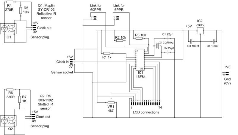
Figure 1: Schematic
Increasingly, the world seems to be moving over to using switch-mode power supplies for this kind of application, as the older style linear power supplies consume more current for a given power output; if you are able to find a 5V switch-mode supply, or a regulated 5V supply, then you may be able to dispense with the on-board regulator circuitry.
The main bulk of the circuit is taken up with IC1, the PIC 16F84, and its attendant components. This chip does two jobs; firstly, it counts the pulses generated by the sensor circuit, and calculates from the number of pulses per second the speed in RPM of the shaft, and secondly, it performs the necessary interfacing functions that are needed to drive the LCD display that will show the operator the results of the RPM calculations.
C2, C3, and X1 form a crystal oscillator that generates a 3.27 Mega Hertz clock to drive the PIC chip. By dividing down the processor's clock signal, the software is able to generate an internal 1-second clock "tick"; in the interval between successive "ticks", the software counts how many times it sees a 5V pulse on the "clock in" pin of the sensor socket (pin 2).
Two further inputs to the PIC allow the user to set links to determine how many pulses will be generated for a complete revolution of the shaft. If neither input is connected to ground, R2 and R3 hold the inputs "high" (+5V), and the software assumes that one input pulse from the sensor equals one full revolution of the shaft. If the link connected to R3 is shorted to ground, then the software assumes 6 pulses per rev (PPR); if the other link is grounded, then the software assumes 60 PPR.
VR1 and the 10 active pins of the LCD display connector form the interface to a "standard" LCD character display. These are readily available in a variety of formats, based around a Hitachi display driver chipset. I have used two variants in this project; one is a 16 character by 2 line display, the other is a 20 character by 1 line display. Both are available from Magenta Electronics. As the 20 character display is internally constructed as two lines of 10 characters joined end to end, it actually behaves from the software point of view as if it is a 2 line display, so I have arranged the firmware in the PIC to be able to drive either variant interchangeably. Which one you choose is a matter of price and performance; the 16 X 2 display costs more, and has better contrast and viewing angle than the 20 X 1 variant.
VR1 allows adjustment of the contrast setting on the display for optimum viewing. Photos 1 and 2 show these two display circuits; Photo 1 is the 2-line display version. For those that are interested in looking at the electrical and command characteristics of these devices in detail, there are data sheets on the Magenta website, and much useful information can be had via the Web.
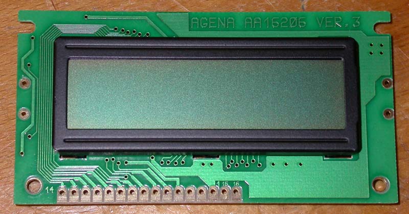
Photo 1: 2 line by 16 character LCD display
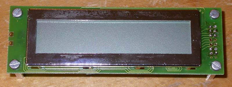
Photo 2: 1 line by 20 character LCD display
The sensing devices are supplied with 0V and 5V lines from the main board, and use two types of infra red detector to generate a 0 to 5 volt "clock" signal to the PIC. The first of these sensors is a SY-CR102 device from Maplin; this is a "reflective" sensor that generates an infra red light beam from an LED in one half of the device, and the other half of the device is a photo transistor that detects received infra red light. If you bring the device to within a couple of millimetres of an IR-reflective surface, such as a piece of white paper, then it will generate a signal. This device can be used very readily to "sense" a shaft's rotation if alternating black and white patches are painted on the shaft, or a printed black and white sensor disk is printed on paper and stuck onto the face of a pulley, for example. Photo 3 gives an example of one of these sensors being used with a pattern of black and white patches painted onto the face of a Myford lathe pulley. I have found that Humbrol black and white enamel paint works very well with this sensor. Interestingly, aluminium, steel and cast iron don't seem to be particularly IR reflective in my experience, even when shiny, so you generally can't get away with just painting/sticking on the black bits, you have to add the white bits too.
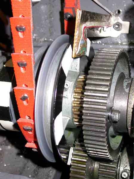
Photo 3:Reflective sensor mounted on a Myford headstock
The second sensor is based around a slotted infrared sensor supplied by RS Components - part number 303-1192. This again consists of an IR-emitting LED and a phototransistor; this time though, the LED is pointed straight at the sensor, so the light beam has to be interrupted to generate a signal. Typically this is done by taking a disc of opaque material (metal or plastic for example), cutting a number of slots or holes in its periphery, and attaching this to the shaft; the sensor is then positioned to straddle the edge of the disc so that the beam is alternately allowed to shine through or is interrupted. Photo 4 gives an example of one of these sensors being used on my Taig (Peatol) mill, with a slotted disc attached to one face of the headstock pulley. The platters salvaged from defunct PC hard disk drives can be useful as a starting point for making a suitable slotted disk.
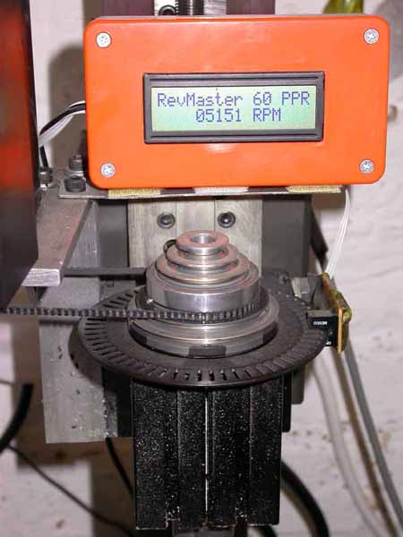
Photo 4: Slotted sensor mounted on a Taig mill headstock
If you already have a sensor that can be made to generate a stream of 0-5V pulses, then this can be substituted for the ones described.
PCB layouts
I have laid out four sets of single-sided PCBs and silk screens for this project that can be found here; two are laid out to the same dimensions as the single line display, the other two the same dimensions as the two line display. There are two variants in each case, the only differences being the lead pitch chosen for the slotted sensor board. The two figures in each case give the track layout, and the "silk screen" information that shows where the various components fit, both arranged as they appear from the non-copper side of the board. The track layout is therefore a mirror image of the layout as you would see it when looking at the copper side.
Apart from the dimensional differences, the two boards (and the two displays) differ in the arrangement of the connection points for the connections between board and the display; the 2-line display has a single row of connecting pads (numbered 1 through 14, but note that pins 15 and 16, which can be used for backlighting, appear just to the right of pin 1 and should be ignored) whereas the single line display has 2 rows of 7 connections (again, numbered 1 through 14). Consequently, on the two PCBs, I have provided corresponding connection points in the same format, laid out so that when the LCD is placed above the component side of the PCB, the correspondence of the connections is direct and obvious.
Both board layouts include layouts for the two variants of the sensor circuit; these differ only in their dimensions, and which you choose to use is dependent upon the physical space that they will occupy on the machine rather than which display you are planning to use.
Etching the PCBs
When printing out the PDFs of the board layouts, be sure that you choose appropriate print options in Adobe Acrobat Reader that ensure the layout is printed without any scaling; otherwise you will end up with boards that are the wrong dimensions for the components.
Those of you that are familiar with the use of UV equipment for PCB production, and have boards coated with UV sensitive resist, can probably skip the following description. However, as the equipment needed for this is expensive for making a one-off board, I decided to try a technique that I had heard of but hadn't used before, which makes use of the properties of the toner used in laser printers and photocopiers (NOT ones based on inkjet technology though!) to create a usable resist for etching.
Laser printers and photocopiers use a black powdered "toner" that is fused onto the paper by means of a heated roller. This toner is basically pigment held in a plastic matrix; it can be caused to melt again with the application of heat, and can be made to stick onto the copper face of the board where it will resist the etching chemicals.
First, you need to prepare a piece of copper clad board to receive the toner resist. Suitable material can be had from Maplin, RS, and so on; it is worth getting good quality fibreglass/epoxy based board rather than the older "paxolin" style board, as the epoxy/glass boards tend to stay flatter and are much stronger. Cut a piece that is the right size for the board(s) you want to lay out, and clean the surface with fine wet & dry paper or a Scotchbrite pad so that it is uniformly bright and clean. This process will get rid of any tarnishing if the board has been stored in less than perfect conditions. Clean the board thoroughly, finishing off with a clean piece of kitchen paper dipped in meths to get rid of the dirt; use a second one if a lot of muck came off onto the paper. Avoid handling the board by anything other than its edges or the non-copper side from now on.
Now, print out a copy of the PCB track layout(s) on your photocopier or scanner/laser printer using 1:1 or 100% scaling. Choose a printing paper that has a shiny surface suitable for inkjet photo printing; these types of paper have a layer of water soluble gum or similar on the surface that helps to release the paper from the toner later on. I found that "PC Line Classic Glossy Photo Paper" from PC World worked well for me. If you have control over the darkness of the image, print it with the highest quality and darkest setting that you can use that is consistent with the image not being degraded by darkening of the white areas. Trim the paper to size. Photo 5 shows two pieces of prepared board, plus the laser printed "transfers", ready for the next stage.
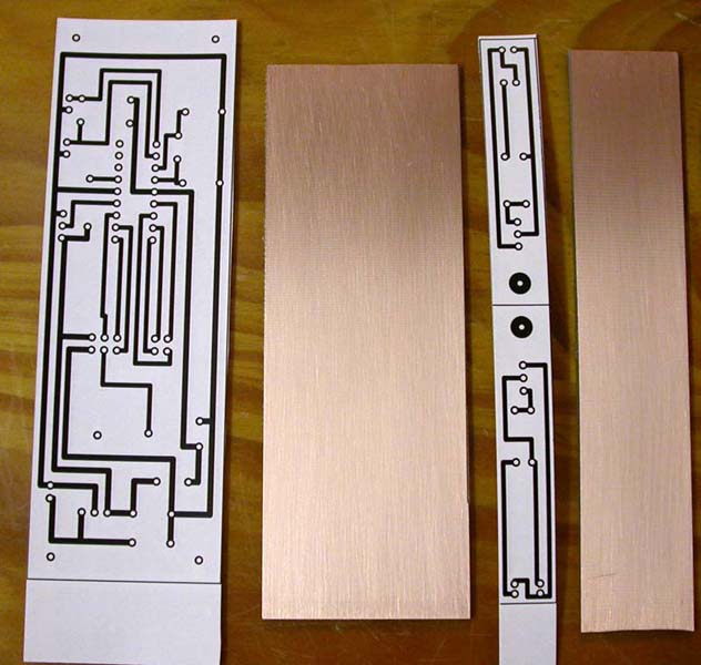
Photo 5: Copper clad board and "transfers" ready to be ironed-on
Next, borrow a domestic iron, switch off the steam, and set the thermostat as high as it will go. Give it as long as it needs to thoroughly warm up.
Now, place the board copper side up on a wooden board that you don't mind damaging (the iron will be hot enough to darken wood significantly in this process, so best not done on the work surfaces or the dining table!), and lay the photocopy of the tracks print-side down on the copper, making sure that it is properly aligned with the board.
Place the iron on top of the paper, making sure that the contact between the base plate of the iron and the paper is even, and press down hard. The toner will start to stick pretty quickly; however, in order to get complete and even adhesion, you will need to maintain the heat, and the pressure, for some while; moving the iron about will help, particularly with steam irons that have holes in their base plates. The length of time needed will be something of a suck-it-and-see exercise; my first attempts at 2-3 minutes were patchy, my second attempts at 5-7 minutes were usable.
Allow the board to cool down completely, and then soak it in hand-warm water for a few minutes. If the process has worked, you will be able to carefully peel off successive layers of paper, soaking between each peel, until there is no paper left and all you can see is black lines on the copper where the toner has adhered to the board. If the adhesion is partial, then go back to the board cleaning stage to remove the toner and start again, this time "cooking" the transfer for longer and with more pressure.
You should now have a board that will etch in the usual etchants used for PCB production; the most common of these is Ferric Chloride solution. I bought this from RS in granule form (part number 237-5413); it comes in a plastic bottle that you simply top up with warm water to make up a stock solution at the right strength; Maplin also supply suitable etchants. All that is needed is to find a plastic container large enough to hold the board when laid flat; an old plastic ice cream container, or an old microwave tray, is perfect for this. Lay the board in the container copper side up and cover it with about ½" of etchant. If the solution is fresh, it should munch its way through the exposed copper pretty quickly - mine was done in about 15-20 minutes. Don't leave the board in longer than needed to clear the unwanted areas of copper; the etchant will undercut the copper at the edges and thin the tracks if you leave it too long, and is perfectly capable eventually of removing all vestiges of copper from the board.
Finally, a going over with the wet & dry or Scotchbrite will take off the black resist leaving clean, bright copper tracks that will take solder very readily.
Drilling and populating the boards
The tracks contain obvious circular "pads" with central holes where component leads pass through the board from the component side for soldering to the tracks; all of these pads need to be drilled with a 1mm drill. This is probably the most tedious bit of the process; I used a Dremel-style high speed drill fitted with a HSS drill bit.
The components can now be inserted in their appropriate positions on the component side, as seen on the "silk screen" layout and soldered to the tracks; any excess lead length is trimmed off afterwards. A DIL socket to match the PIC chip is soldered in place rather than soldering the PIC directly to the board; this allows the chip to be readily removed and re-programmed later on if you need to make changes to the firmware. Take note of the orientation of the PIC chip as indicated on the silkscreen drawing; the DIL socket has a notch at one end that corresponds to a similar notch on the top surface of the chip.
There is room to fit the voltage regulator device so that it lays flat on the board; it should not be necessary to fit a heatsink to this as the circuit is not very power hungry.
With either board, only pins 1-6 and 11-14 of the LCD display need to be connected to the corresponding pins on the main board. This can be done using lengths of stranded connecting wire, or ribbon cable, depending on what you have to hand. On the single line display version of the board, I used a 14-pin "header" soldered to the board, and an IDC connector on the end of a short ribbon cable, so that the display could easily be detached from the board and swapped for the 2-line display during testing; however, this is an unnecessary elaboration for most purposes.
Note that there are wire links that need to be soldered in place on both main boards; one link on the single line display version, four links on the two line display version. The positions of these links are shown on the silk screen layouts.
Populating the two sensor boards is pretty straightforward. The reflective sensor is rectangular, but has one corner chopped off; this is oriented as shown in the silk screen layout, with the active surface pointing away from the board. The slotted sensor also has to be correctly oriented; the LED is translucent, whereas the phototransistor is solid black.
Photo 6 and Photo 7 show the main board of the single line display version, with all components inserted; Photo 8 and Photo 9 show the top and bottom views of the two versions of the sensor board (reflective and slotted sensors). You will notice from the photos that I have coated the copper tracks and component leads on the two sensor boards with epoxy resin ("Araldite" Rapid) to protect them from physical and electrical damage.
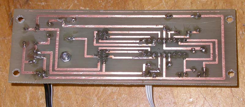
Photo 6: Track side - main board
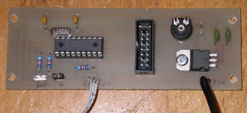
Photo 7: Component side - main board
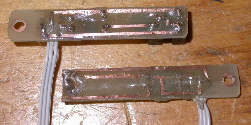
Photo 8: Track side - sensor boards
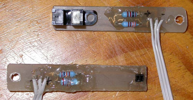
Photo 9: Component side - sensor boards
The following table shows the parts list for the project:
Component number
Value
Comments
R1
1K Ohms
¼ Watt
R2
10K Ohms
¼ Watt
R3
10K Ohms
¼ Watt
R4
270 Ohms
¼ Watt (Reflective sensor)
R5
10K Ohms
¼ Watt (Reflective sensor)
R6
330 Ohms
¼ Watt (Slotted sensor)
R7
1k Ohms
¼ Watt (Slotted sensor)
IC1
PIC 16F84
Pre-programmed from L.S. Caine Electronics
IC2
78055V
linear voltage regulator
C1, C2
22 pico Farads
C3, C4
100 nano Farads
X1
3.27 Megahertz Quartz crystal
DO NOT substitute a different frequency, as this will make the readings inaccurate!
VR1
4.7K Ohms
Miniature PCB mounting type
Q1
Maplin SY-CR102
Reflective IR sensor
Q2
RS 303-1192
Slotted sensor
LCD Display
16 chars X 2 lines or 20 chars X 1 line
Magenta
Box
RS 281-6829
For two-line display
Box
RS 281-6835
For single-line display
Final assembly
I found that RS make a range of plastic boxes that are about the right size for this project; part number 281-6835 is suitable for the (longer) single line display, and part number 281-6829 is suitable for the two-line display.
I used 20mm long, hexagonal section, 3mm tapped chromed brass pillars as stand-offs to assemble the single-line display to its board - these are available from RS, part number 222-424, but could easily be made from lengths of 5mm AF hex Brass bar axially drilled and tapped M3 (Here at last is the metalworking content of this project!). The assembly then dropped nicely into the base of the plastic box, as shown in Photo 10. The PCBs have been laid out so that the tracks keep well clear of the four corner mounting holes; however, with the LCD display boards, this is not the case. This means that if you use metal pillars and screws as I have done, you will need to fit Nylon insulating washers under the screw heads and between the display board and the pillar in order to ensure that you don't inadvertently short out tracks on the display board. The display dimensions are such that the complete circuitry will be supported on the "fins" at each end of the box, at just the right height for the display to be viewed through the lid.
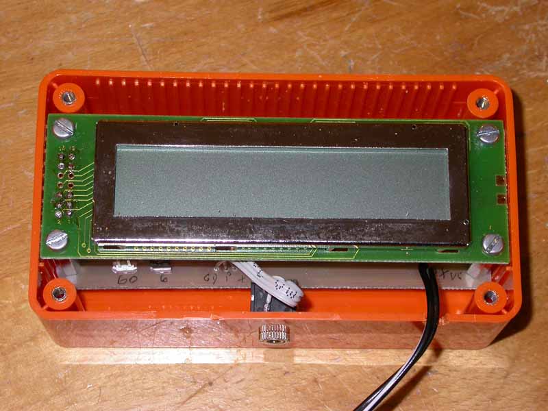
Photo 10: Unit installed in a box
Note that I used a standard mini stereo jack socket for the sensor connection; if you are planning to use the unit with a specific sensor, then hard-wiring the sensor to the board is an alternative, but I wanted to be able to swap sensors for testing purposes. A cut-out in the box lid to reveal the display, and a decorative "window" attached to the outside to protect the display and cover up the gaps, and the end result is as shown in Photo 11.
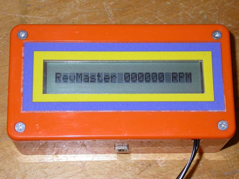
Photo 11: Lid and display window fitted
Photos 12 and 13 show the equivalent arrangement for the two-line display version. In this case, shorter pillars are needed (around 16mm if I recall correctly), and I found that the most convenient mounting strategy was to make a cutout in the lid and then stick the display into the cutout using Pritt double sided foam "sticky pads".
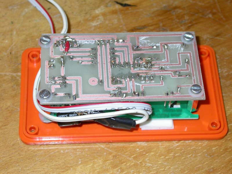
Photo 12: 2-line display version - interior view
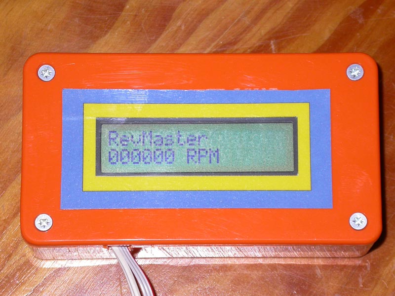
Photo 13: 2-line display version - display window
Mounting the rev counter on a mill
As my X3 mill, recently converted to CNC (the conversion featured in MEW issue 113), has a variable speed spindle motor, I decided to fit a rev counter to it, using a reflective sensor with black and white marks painted on an exposed area of spindle (see Photo 14). Fitting the sensor is pretty straightforward - I made a simple right-angle bracket from some thin steel strip, attached the sensor to that with a M3 screw and nut, and attached the bracket to the underside of the mill head so that the sensor could be brought into close proximity with the rotating black and white patches (see Photo 15). The circuitry in its box was attached to the front of the head using more double sided sticky pads, as shown in Photo 16.
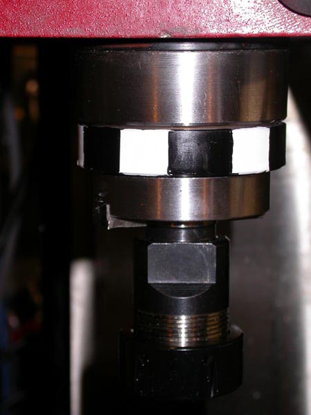
Photo 14: X3 mill spindle with markings for reflective sensor
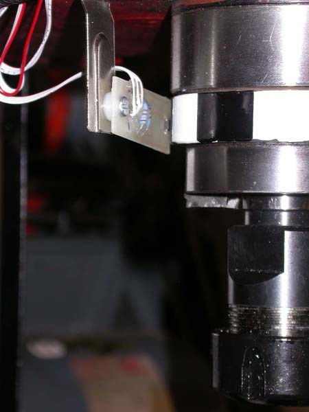
Photo 15: Sensor installed on X3 mill head
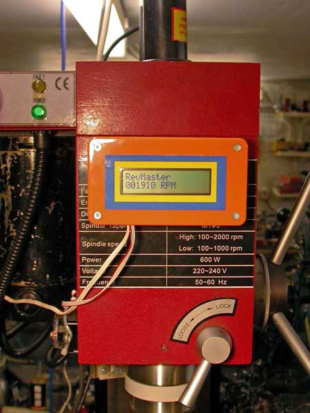
Photo 16: Display unit installed on X3 mill head
You will find with this sensor that it needs to be approximately 1mm from the surface it is sensing; too far and it doesn't pick up a signal, too near, and the device shields itself from its own light source. However, once the right positioning has been found, they seem to work pretty reliably.
Choosing a sensor and a measuring range
The SY-CR102 reflective sensor device seems to be capable of generating up to 1400 pulses per second, although according to the Maplin catalogue the rise and fall times for the phototransistor are both 1ms, which would equate to around 500 pulses per second. So, taking the middle ground and assuming that it is realistic to expect up to 1000 pulses per second from one of these devices, a measuring range of 1-1000 RPM would result if you had 60 pairs of marks (60 black, 60 white) on the shaft. This would be suitable for measuring RPM on a slow turning shaft, but not for the more general application of measuring RPM on a lathe or mill spindle. Reducing the number of black (and white) segments to 6, the measuring range becomes 10-10,000 RPM, which is a more generally useful range for workshop machinery. For really high-speed measurement, a single black (and white) segment allows the measurement range to extend to a terrifying 60-60,000 RPM.
The slotted sensor (RS part number 303-1192) quotes rise and fall times of 5 microseconds, so appears to be capable of generating pulse trains of the order of 100KHz or so; I have not yet managed to generate more than 14KHz in my tests to date, but this is a reflection on the slow rotational speed of the machines in my workshop rather than the capability of the sensor. This significantly increases the range of RPM that the meter can measure; with 60PPR, the measuring range is a very respectable 0-14,000 RPM, rising to a bone-jarring 60-840,000 RPM if the slotted sensor was to be used with a single slot.
The choice of which sensor is appropriate will depend on the physical layout of the machine concerned and what kind of measuring range is desired. Significant issues here include:
- Size of black/white marks - it is difficult to get to 60 marks onto a small shaft and still have them large enough for the reflective sensor to "see" them - they need to be at least 2mm wide. So in general if you want to use the 60PPR range, you will need to use the slotted sensor and a disk with 60 slots or holes in it.
- Oil contamination can be a problem with the black and white marks used for the reflective sensor; you need to choose a location where they won't get covered with oil.
- Slotted disks can be difficult to attach in some circumstances; similarly, in others, there may not be an obvious place where you can paint on suitable reflective marks.
- Experimentation will be needed to choose the right paints to create a reflective sensor arrangement; Humbrol enamels have worked well for me.
- If you use the slotted sensor, note that the disk also needs to be painted black to be non-reflective, otherwise it can give spurious signals.
- The reflective sensor needs to be very close to the shaft it is sensing - 1-2mm or so. The width of marks must be larger than the size of device, so a minimum width of 2mm is a requirement here.
- Mounting the sensor in a place where it will not suffer physical damage is essential!
- So far, I have not tested the circuit of the meter itself to determine what the upper limit of the counting mechanism is, although I have demonstrated that it can count at least 14,000 pulses per second. In the current software configuration, the count of pulses is held in an integer variable that can hold a maximum count of 32,767, so this represents a theoretical maximum even if the counting mechanism can handle higher rates.
Suppliers and other contact details:
1. For copies of the "C" code and HEX files for this project, or for PDFs of the PCB layout diagrams, see this page
2. "C" development systems and PIC programming tools used by the author can be obtained from Forest Electronic Developments (FED), 12 Buldowne Walk, Sway, Hampshire, ENGLAND, SO41 6DU, Tel: 01590 681511, Website: http://www.fored.co.uk
3. RS Components: https://uk.rs-online.com/
4. Maplin Customer Service: 0870 429 6000 Website: http://www.maplin.co.uk/
5. Magenta Electronics Ltd., 135 Hunter Street, Burton-on-Trent, DE14 2ST U.K., Tel: 01283 565435 Website: http://www.magenta2000.co.uk
6. Microchip Technology Inc website: http://www.microchip.com