Copyright © Tony Jeffree, 13th May 2000. All rights reserved.
Many lathes and milling machines are now being supplied with drive systems that make use of electronic variable speed motor controls. Taking advantage of this trend, I recently fitted a Sherline motor and variable speed controller to my newly acquired Taig CNC milling machine. This was partly in order to improve the torque available to the spindle, and partly because of the convenience of not having to change and adjust the drive belt every time I changed the spindle speed. The one disadvantage of the Sherline drive is that, in common with most variable speed drives supplied to the model engineering market, there is no means of determining what spindle speed has actually been set. The controller simply has a knob that you can turn from "slow" to "fast" or any point in between. For most purposes, I have not found this to be a big problem - I have simply used trial and error to set a spindle speed suitable for the material, rate/depth of cut and cutter in use. However, as my rate of end mill consumption was getting to be an issue, I felt that I ought to pay more attention to setting the recommended spindle speed for the cutter diameter and material, especially when working with harder materials. A first step in the right direction would clearly be a means of calibrating the speed control knob so that a reasonably accurate speed could be set. Of course, a means of continuous, direct measurement of the rotational speed would be the ideal.
A second and related problem is determining the surface speed (often measured as SFM or Surface Feet per Minute; or I guess, SMM if you are working in metric units) of a work-piece in the lathe. Knowing the diameter (and hence, circumference) of the work-piece, and knowing the spindle RPM, it is of course possible to work out the surface speed. However, it is potentially useful to have a means of directly measuring the surface speed of the material, especially as the diameter of the work-piece tends to reduce as machining progresses, and repeated recalculation is time consuming.
With these thoughts in mind, I set about investigating the options available for accurately determining spindle and surface speeds. The following sections describe the results of my experiments in this area to date, and offer a number of options of varying complexity to suit different applications and purses.
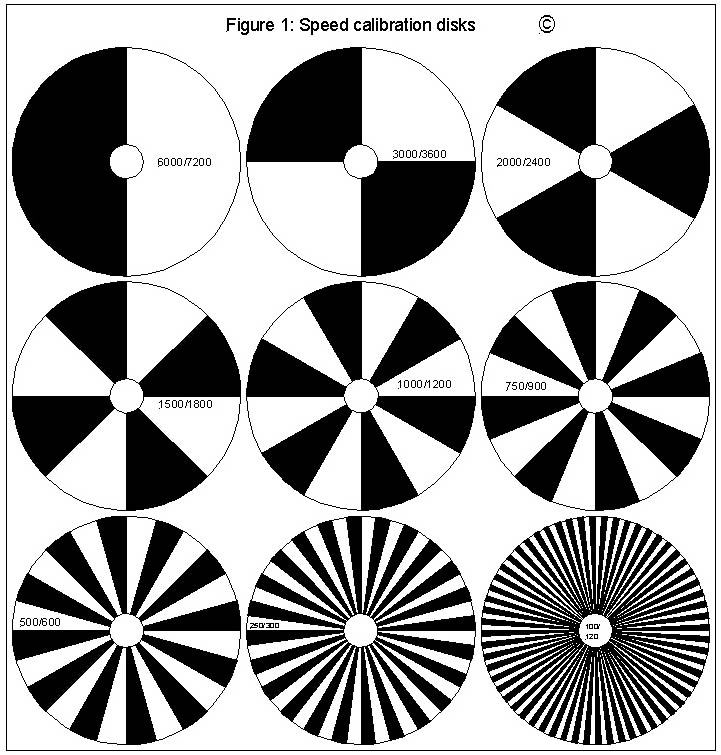
A good starting point seemed to be to find a simple method of calibrating the knob on the Sherline motor's speed controller. My adaptation of the Sherline motor for use in the Taig mill retained the six-speed pulleys of the original Taig drive; however, as I now use only one of the six speed ranges for most of my work, I felt that calibrating the knob just for this range would suffice. This something of a "Catch 22" problem. If I had a means of directly measuring the spindle speed, I would not need to calibrate the knob; however, without a means of measurement, calibration is impossible. Thankfully, the solution is relatively straightforward, and makes use of "stroboscopic" discs similar to the ones that used to be used for checking the rotational speed on hi-fi turntables. These discs make use of the fact that a light source powered by AC current varies in intensity with a frequency exactly twice the AC frequency. The discs are divided into a number of alternating black and white sectors of equal size. If you spin one of these discs at a rotational speed such that the time between the high intensity peaks of the light source is exactly equal to the time for the disc to rotate 1/Nth of a revolution (where N is the number of white or black sectors) then the pattern of sectors appears to be stationary. For example, if the disc has two white sectors (and two black ones), then with a 50-Hertz light source, the pattern on the disc will "freeze" at 3000 RPM (i.e., 50 RPS). Figure 1 shows a set of these discs, giving a range of speed measurement from 100 to 6000 RPM when illuminated by a 50-Hertz light source (i.e., powered by UK mains electricity) or from 120 to 7200 RPM when illuminated with a 60 Hertz lamp (US mains). Each disc is marked with the pair of speeds that it will indicate; in each case, the smaller number applies to 50-Hertz supplies. It is worth noting that the discs can also indicate multiples of their base rotational speed; for example, the 3000 RPM disc will also appear to "freeze" at 6000 RPM. However, the image obtained at these higher speeds is less intense.
Using these discs is a matter of printing them, cutting them out and attaching them to a suitable spindle end, for example with double-sided tape. Photo 1 shows one of the discs attached to the end of the Taig spindle's drive pulley. In order to calibrate the Sherline speed controller knob, I simply adjusted the spindle speed until the strobe image stabilised and then marked the position on an improvised paper dial stuck onto the face of the controller (see Photo 2). I found that different light sources behaved very differently with these disks; I failed to get them to work at all when using one of the new "energy saver" fluorescent bulbs, but had more success with a conventional filament lamp. This approach provides quick and easy means of calibrating a speed controller dial that subsequently allows the speed to be set "near enough" for many uses of a lathe or mill.
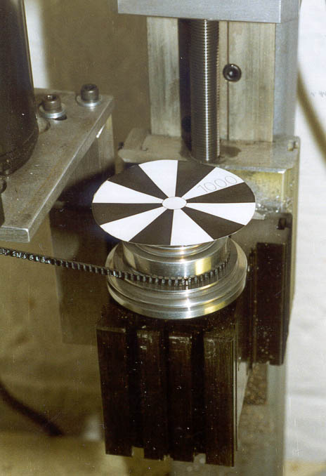
Photo 1: Strobe disc attached to the milling spindle with double sided tape
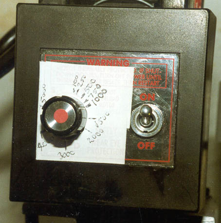
Photo 2: Sherline motor controller after calibration
One of the techniques that I came across during my search for a solution to the measurement problem was to use a permanent magnet DC motor as a dynamo. Any such DC motor will generate a DC output voltage when its armature is rotated; most will show a nicely linear relationship between the output voltage and the spindle RPM. Figure 2 shows an example of such a relationship; the motor was one that I salvaged from a small 12-volt car tyre pump that had seen better days. Plotting the curve was a matter of clamping the motor spindle in the mill using a suitable collet (see Photo 3), using the strobe discs to adjust the spindle speed, and then measuring the output voltage using a multi-meter. With care, the motor body can simply be held steady by hand prior to starting the mill, as very little force is required to spin the motor under these "no load" conditions. DO NOT let go of the motor while the spindle is running, unless you wish to turn the motor into an impromptu projectile, damaging the collet and motor shaft in the process. Clamping is clearly the better option for the faint hearted! The result with this motor was as near a straight line as makes no difference over the range 100-4000 RPM, so this technique clearly has possibilities as a means of measuring intermediate speeds once the motor/dynamo has been calibrated. The output of this particular motor proved to be approximately 7/8 of a millivolt per RPM.
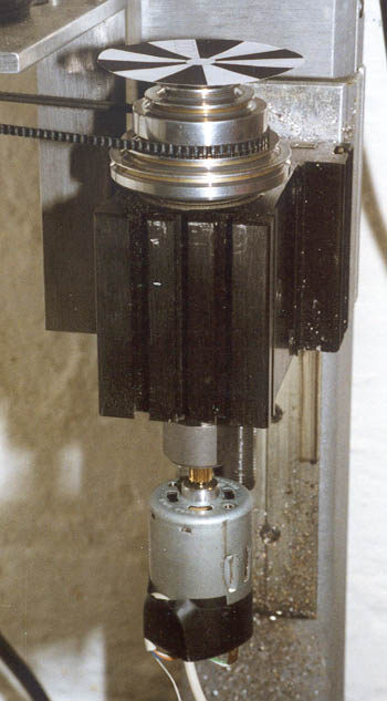
Photo 3: DC motor held in the milling spindle by its shaft
The current output from this motor also shows a linear relationship with spindle speed. Current meters generally have as low a resistance as possible, so as not to impede the current flow being measured. A current meter attached across the motor terminals would effectively short out the motor armature, creating significant drag. In contrast, voltmeters ideally present no load whatever to the signal being measured, in order for the meter not to reduce the voltage being measured. Consequently, I have chosen to use voltage measurement rather than current measurement in these experiments, but either is possible.
There are many options for providing a suitable means of measurement. Electrical multi-meters and panel meters are available in many shapes and sizes, and can be surprisingly cheap. For example, Maplin currently list a pocket-sized analogue multi-meter (part number YJ06G) for about £7 and a pocket sized digital multi-meter (part number ZA37S) for about £20. Panel meters can also be obtained from about £5 and adapted for the purpose. A great advantage of digital meters for this application is that the polarity of the applied voltage is not important; the display simply indicates + or - accordingly.
With analogue meters, it is obviously necessary to connect the motor to the meter the right way round. In practice it is no great hardship to simply re-connect the meter leads with the reverse polarity when necessary. Alternatively, you can use a centre-zero meter where the meter needle deflects to the left with a negative signal and to the right with a positive signal. The disadvantage of the centre-zero approach is that the scale is effectively cut in half, reducing the meter's resolution.
Having obtained a suitable meter, the next problem is to persuade the meter to give a reading that can be interpreted directly in RPM. The motor mentioned above generates 7/8 of a millivolt per RPM, so attaching a meter that measures in millivolts gives a close approximation to a direct reading of RPM. For more accurate measurement, you could obviously take the meter reading and translate it via the graph (or a calculator) to give the actual RPM value; however, this could be a little tedious. With an analogue meter, the solution can be straightforward; you simply re-calibrate the dial of the meter to read in RPM by attaching a new paper scale with appropriately spaced markings.
With either a digital or analogue meter, it is also possible to adjust the sensitivity of the meter, by means of series or parallel resisters, to suit the behaviour of the motor. For example, if you had a meter that measured 0-10 volts, and a motor that generated 15 volts at 10000 RPM, then you could adjust the meter's sensitivity to 2/3 by connecting it via a series resistance with a value equal to half the meter's internal resistance. A reading of 10 volts on the meter would then correspond to 10000 RPM. If you are using a multi-meter on one of its voltage ranges, the internal resistance can be calculated from the "ohms per volt" figure quoted for the meter. The Maplin analogue pocket multi-meter is quoted as 2000 ohms per volt, so when set to its 10 volt range, the resistance between the measuring terminals is 20000 ohms. An additional series resistance of 10000 ohms would create the desired scale correction for this example. For the more enterprising constructor with knowledge of electronics, it would be a simple matter to modify the in-built shunt and multiplier resistors in the meter in order to produce a unit with several RPM ranges, all tuned to the behaviour of the chosen motor/dynamo. This is a particularly attractive option in the case of the Maplin analogue pocket multi-meter, as it neatly packages the meter movement and switching circuitry at a price that would be hard to match using individual components, plastic cases and so on – not to mention the saving in construction time.
Once the motor has been calibrated, and a suitable meter attached, the motor spindle can be coupled to a rotating shaft in order to provide a direct measurement of spindle speed. The coupling used can be permanent or temporary; flexible couplings can be easily made from short lengths of rubber tube, for example. Permanent couplings can obviously be achieved by using pulleys or gears; however, it is worth considering the potential life span of the dynamo before choosing a permanent attachment to the machine. A means of temporary coupling, allowing hand-held use, can be made by attaching a small rubber cone to the end of the motor shaft, and pressing this against the end of the rotating shaft, with the motor and shaft in line. This could be either an external cone (a conical point) or an internal cone, depending upon the application.
Attaching a rubber disc, or a disc with a rubber edge, to the spindle of a DC motor/dynamo, calibrated as described above, offers the possibility of providing a direct measurement of surface speed on components mounted in the lathe. If the circumference of the disc is exactly 1" (i.e., the diameter is exactly 1/pi", or approx. 0.318") then pressing the disc against the surface of a rotating work-piece will give a direct reading of surface speed, in inches per minute, if the motor/meter has been calibrated in RPM. Similarly, a disc with a circumference of 12" (i.e., 12/" diameter, or approx. 3.82") would allow direct measurement in SFM. A suitable 1" circumference rubber disc could be made by turning down a rubber tap washer; the larger disc could be made by turning a disc of plywood, and then gluing a broad elastic band (the kind the Post Office use for large bundles of letters) to its circumference with contact adhesive. Needless to say, you would have to allow for the thickness of the band when turning the diameter. Photo 4 shows this technique in use; the motor has a 12" circumference disc attached.
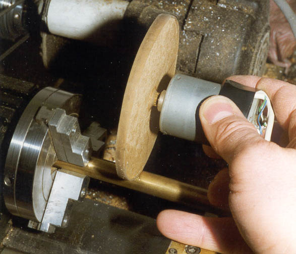
Photo 4: Measuring surface speed
Having proved the approach, I then set about devising a motor/meter combination using readily available components. Model Motors Direct supply a wide range of small motors that can be pressed into service as impromptu dynamos. I have based this project around their "M3 Rowe motor", as this seems to have suitable characteristics and is a standard stock item at MMD. Figure 3 shows the performance of this motor - again, the plot of spindle speed against output voltage is nicely linear over the 100-4000 RPM range. The output voltage is 2.4 millivolts per RPM. I have taken this motor up to 6000 RPM, at which point it is generating nearly 15 volts. As this is somewhat above its theoretical operating voltage range of 6-12 volts when used as a motor, I suspect that this treatment may not be very good for it!
The meter for this project is the Maplin pocket-sized analogue multi-meter (part number YJ06G) mentioned earlier, and shown in Photo 5. The internal components can be seen in Photo 6; the board is marked with the component numbers. In its standard form, this meter measures 10, 50, 250 and 500 volts (DC or AC), 0.5, 50 and 150 milliamps, plus a resistance range. The very simplest approach with this motor and meter combination is to use only the 10 volt range; this would nicely cover the 100-4000 RPM range shown in Figure 3. A very close approximation to the true RPM reading can be had simply by using the 0-10 scale on the meter dial, and mentally multiplying the measurement by 400. This has the obvious advantage of simplicity, and also allows the meter to be used for its intended purposes. To make reading the meter easier, an RPM scale could be added to the dial with sticky paper/markers, and calibrated using the strobe discs and/or the graph in Figure 3. If this were to be added to the outer surface of the meter window, it need not permanently obscure any of the existing scales.
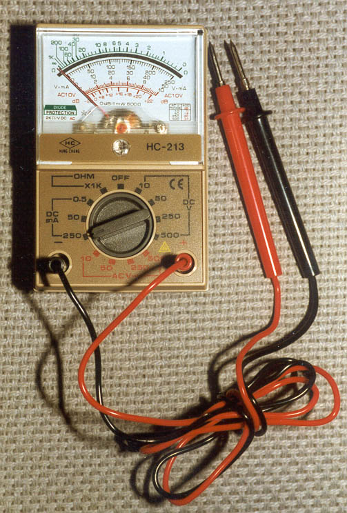
Photo 5: Cheap analogue multimeter suitable for conversion to a RPM meter
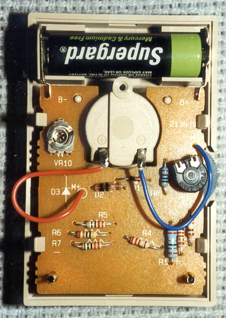
Photo 6: Internal component layout of the meter before conversion
However, there is something to be said for having switchable measuring ranges, so that the sensitivity of the meter can be adjusted to the job in hand. As this meter is so cheap, I decided to treat it as a ready-boxed meter movement and multi-way switch, and to modify its measuring ranges to suit the application. I decided to abandon all its other potential uses, and to re-calibrate the voltage ranges to read 500, 2500, 5000 and 10000 RPM. These correspond to voltage measurement ranges of 1.2, 6, 12 and 24 volts respectively with the chosen motor.
On testing, full-scale deflection of the meter movement appears to require 200 micro amps, and the coil resistance was measured as 348 ohms. In order to determine the value of series resistance needed to convert the meter to read a voltage range, you simply calculate the value of resistance required to produce a current of 200 micro amps with the applied voltage, using the Ohms Law equation E=IR (where E is the voltage in volts, I is the current in amps, and R is the resistance in Ohms). Subtract the meter resistance from this figure to give the resistance value that must be placed in series with the meter to read the desired voltage range. So, for the 500 RPM range (0-1.2 volts), the calculation yields 8,696 Ohms (8.696K Ohms), which when corrected for the meter resistance, leaves 8.348K as the series resistance needed for this range. The way the switching circuitry on the meter works for the voltage ranges is to add on successive resistor values for the higher ranges. So the additional resistance needed to generate the 2500 RPM range is 34.78K, a further 43.48K for the 5000 RPM range, and 86.96K for the 10000 RPM range.
This range of resistance values didn't happen to coincide with the resistors in my bits box at the time, so I decided to add a "shunt" resistance across the meter, to alter the basic current measuring range to suit the resistors in my box. I did this by incorporating one of the potentiometers on the exiting board, in order to allow some fine tuning of the measuring scale as well. The nearest match I found for the 500 RPM range resistor was 4.7K, so I based the other range values on this, and reduced the meter sensitivity accordingly.
The existing meter uses the same range resistors to measure AC and DC volts. As the AC measurement circuitry only used a half-wave rectifier, I chose for reasons of simplicity to abandon any attempt to retain the AC ranges, so the final modifications result in identical DC measuring characteristics on the AC and DC volt ranges. All other measuring ranges are non-functional.
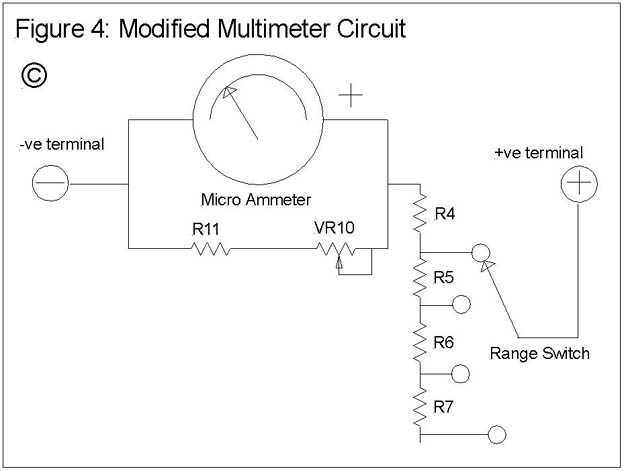
Construction starts by removing the circuit board from the meter housing by unsoldering the two wires to the meter movement and carefully prising the board out of the plastic clips that hold it in place. Using a small soldering iron, carefully remove all the components from the board, leaving only the -ve meter lead (blue insulation) in place. I also removed the battery clips as these are not required, but this is not essential. The modified board, with its new components in place, can be seen in Photo 7. As can be seen in the photo, I used pairs of resistors to make up the R5 and R6 values to suit components I had to hand. Re-solder the potentiometer that was marked VR9 on the board, but in the position previously occupied by VR10; i.e., on the left of the board. The plastic knob that was fitted to VR9 should be removed before this component is re-fitted. Solder new resistors into the positions previously occupied by R4 through R7, as indicated in Table 1. The additional resistor, R11, is soldered between the right-hand end of the D1 position and the left-most of the three VR9 holes. The red meter lead is re-fitted at the left-hand end of D1. A wire link is soldered from the top end of R3 to the right-hand end of D2. Figure 4 shows the resultant circuit in schematic form.
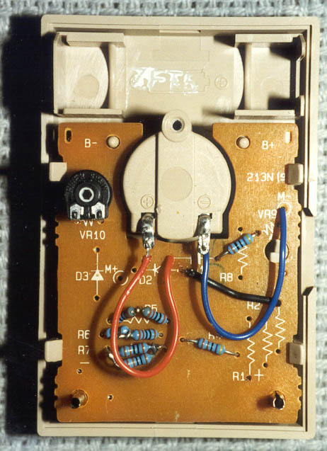
Photo 7: Meter component layout after conversion
COMPONENT
VALUE
MAPLIN PART #
R4
4.7K Ohms
G4K7
R
20K Ohms
G20K
R65
24K Ohms
G24K
R7
47K Ohms
G47K
VR10
1.4K Ohms
(Previously VR9)
R11 (Not marked on board)
470 Ohms
G470
The board can now be replaced in its clips, and the leads re-soldered onto the meter terminals. The two probes at the ends of the external meter leads are removed, and the two leads soldered onto the appropriately coloured tags on the motor. Apply a turn of insulating tape round the motor body, fold down the tags flush with the body, then another couple of turns of tape to insulate the connections and give strain relief to the leads. The motor leads can be twisted together for neatness, and a piece of tape used to prevent untwisting. Plug the leads into the meter sockets, and the meter is ready for testing. You should find that rotating the motor clockwise (when viewed from the spindle end) will make the red lead +ve; therefore, the leads should be connected to the meter red lead to right hand socket in order to give the right meter deflection. If the motor is spun anticlockwise, the meter leads will need to be unplugged and reversed. Cover the area around the meter's range switch with sticky paper, and mark the new ranges. The old 10V range becomes 500 RPM, 50V becomes 2500 RPM, 250V becomes 5000 RPM and 500V becomes 10000 RPM. As both the AC and DC ranges are identical now, it is really only necessary to mark one set.
Couple the meter to a suitable rotating shaft (a 1/8" diameter collet in the mill or the 3-jaw directly onto the shaft in the lathe); clamp the motor body if you prefer, or hold it to prevent its rotation. Set the meter switch for the 2500 RPM range, and re-fit the potentiometer knob to the back of VR10. Carefully run the spindle up to 2000 RPM (measured with the 2000 RPM strobe disc) and adjust the potentiometer to give a reading of 200 on the 0-250 scale. Remove the potentiometer knob, taking care not to ruin the adjustment in the process, and re-fit the plastic back of the meter housing. The device is now ready to measure RPM on all four ranges; the addition of the rubber-edged disc already described above will convert it into a device that will directly read SFM.
Photo 8 shows the completed device, along with the SFM adapter disc. The latter was turned down from a piece of 4mm thick MDF, a brass boss with a 1/8" axial hole Araldited into its centre, and a broad elastic band stuck onto its outer edge. The hole in the boss can be made so that it is a push fit onto the motor shaft, to allow it to be easily exchanged for other types of temporary coupling if need be.
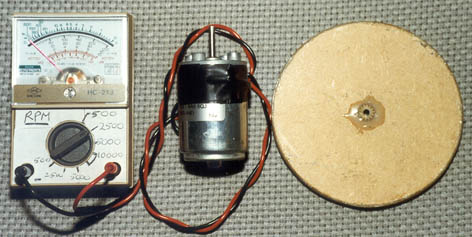
Photo 8: Completed analogue RPM/surface speed meter
The component suppliers now offer a wide range of devices, semiconductor and otherwise, that can be pressed into service as a means of providing measurements of rotational speed. The most likely of these to be of use to the amateur constructor are the ones that are based on the use of infrared emitters and detectors. LEDs that emit infrared light are freely available as discrete components, as are photosensitive transistors that will respond to an infrared light source. Phototransistors behave much like a switch; when not illuminated, they present a very high electrical resistance, which drops to almost zero when illuminated. This behaviour can be used to generate a pulse train that can then be converted into a measurement of RPM by counting the number of pulses that occur during a known time interval.
There are essentially two ways that these infrared devices can be used to generate a pulse train from a rotating shaft. The diode light source can be pointed directly towards the phototransistor, and the beam of light interrupted, for example by a disc with teeth or slots cut in its periphery (sometimes known as an encoding wheel). Alternatively, the light from the diode can be reflected off a suitable surface that is alternately infrared reflective and absorbent (black surfaces tend to absorb infrared; white or clean metal surfaces tend to be reflective). Pre-packaged infrared devices are available to meet both of these approaches; Maplin's Slotted Opto Switch (part number CH18U) is an example suitable for the first approach, and their Photo Reflective Infra-Red Sensor (part number UK81C) is an example suitable for the latter. Photo 9 shows these tow devices (the Opto Switch on the left, the Photo Reflective Infra-Red Sensor on the right), with a discrete IR sensitive transistor and IR emitting diode in between them. The penny piece serves to give a size indication.
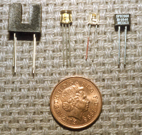
Photo 9: Optoelectronic sensor components
Of the two, the photo reflective approach is by far the easiest to use, as it doesn't involve cutting slots in an encoding wheel. Photo 10 shows the spindle pulley of the Taig mill, with six black marks applied using a heavy black felt-tip pen in order to test out one of these devices. The contrast between the bare aluminium surface and the pen marks is sufficient to generate a pulse train from a photo reflective sensor. Accuracy of marking is unimportant, and can therefore be done freehand if the number of marks is small. The only thing to watch is that, if the marks are too close together, or if the marks are too narrow, the sensor may not be able to "see" the transitions between the reflective and absorbent surfaces. Getting this right will depend upon the physical dimensions of the sensor; as a rule of thumb, the width of the marks, and the width of the reflective spaces between them, must be greater than the dimensions of the sensor package. The use of an encoding wheel to interrupt a beam is necessary if a large number of pulses per rotation are needed, as the beam of infrared light generated by these devices is narrower than with the reflective devices.

Photo 10: Taig pulley marked with a felt-tip for the reflective sensor
The next problem is to take the pulse train generated by such a device and turn it into a measurement of RPM. The more sophisticated digital multi-meters are able to give a direct measurement of the frequency of an applied alternating signal. Plug mine into the mains and it reads 50 Hertz, for example (although some may not be capable of handling such high voltages for frequency measurement - do check before trying this, and of course, use the usual precautions when handling mains voltages). My multi-meter is one that I picked up very cheaply in a recent Tandy sale (Radio Shack catalogue number 22-7220 "Wide Frequency Measuring Digital Multi-meter" - however, this may not be available any longer, as Tandy seem to be giving up this line of business in the UK). Maplin sell a range of meters with similar capabilities, for example their PG012 meter (part number GW20W, at around £40) seems to have a suitable frequency measurement range. When purchasing a meter for this purpose, take note of the frequency range that it measures over. The high end of the range will almost certainly not be a problem; mine is capable of measuring in megahertz. However, the low end of the frequency range may be problematic. The low end of the range, coupled with the number of marks on the shaft, will determine the lowest measurable RPM from the set-up. For example, with a meter capable of reading from 100 Hertz upwards, and with a single mark on the shaft, 100 Hertz corresponds to 6000 RPM. In order to make this useful for lower speed measurement on a lathe or mill, you would need to use a larger number of marks on the shaft or slots in the encoding wheel - for example 60 would give a direct RPM reading from 100 RPM upwards. My Tandy meter appears to be able to register from 1 Hertz upwards. The only problem I found when using the Tandy multi-meter is that its sampling period is 1 second, so the display does not respond immediately to changes in spindle speed. However, the longer the sampling period, the lower the frequency that the meter will be able to measure, so this is something of a trade-off. In practice, waiting a second or two for the reading to stabilise is not a real problem.
Figure 5 shows a simple circuit that will allow an Infra-Red sensor device to generate a pulse train suitable for feeding into a multi-meter with frequency measuring capability, and Photo 11 shows a completed sensor made to this circuit, attached to the spindle of the Taig mill. For convenience I have moved the black sensor marks down to the fat end of the pulley, as this made placing the sensor and attaching the unit more convenient. Clearly, the mounting and construction arrangements will differ according to the machine in use.
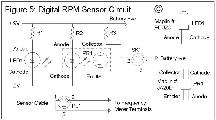
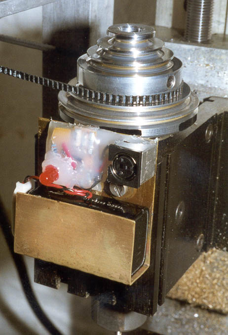
Photo 11: Digital RPM sensor in position on the mill spindle
Components and part numbers are shown in Table 2. The circuitry was assembled on a small rectangle of strip board; the whole thing is assembled on a simple bracket made from brass sheet, held onto the spindle body with a T-bolt. The miniature DIN socket serves two purposes; firstly, to connect the external meter, and secondly, to switch on the power supply to the circuit. The red LED simply reminds you to unplug the meter (thus switching off the power) when you're done. The sensor device used was Maplin's Photo Reflector SY-CR102 (Part number JA26D), which is physically smaller than the one mentioned above - its package is about 2mm square. This device is let into a small slot in the upper edge of the brass bracket, and the circuitry and DIN socket held in place (and insulated from the brass bracket) with glue from a hot melt glue gun. The PP9 battery can be seen in the clip at the bottom of the bracket. Although the circuit diagram shows a supply voltage of 9 volts, this is not critical, and can be varied for other supply voltages by choice of different resistor values. The sensor is quoted as having a rise and fall time of 1 millisecond, so this would seem to place an upper limit of 500 Hertz on the pulse train that it can generate. With 6 marks on the rotating shaft, this represents a measuring range of up to 5,000 RPM; with a single mark, it should be possible to use this device to measure spindle speeds up to 30,000 RPM.
COMPONENT
VALUE
MAPLIN PART #
PR1 (Photo Reflector SY-CR102)
JA26D
LED1 (Red LED)
PD02C
R1, R2
470 Ohms
G470
R3
10K Ohms
G10K
SK1 (Mini DIN socket)
3 pin
JX13P
PL1 (Mini DIN plug)
3 pin
JX01B
Strip Board
100mm X 25mm
JP46A
Battery connector
PP3-type
NE19V
The photo reflector comes in a square black plastic package that has two rectangular indentations on the active side (the side you point at the rotating surface) and two pairs of wire leads. One corner of the package is chopped off to mark the ANODE lead. The lead directly in line with it, emerging from the opposite side, is the CATHODE. These two are the leads for the IR emitter diode. The other lead that emerges from the same side as the anode is the EMITTER of the IR detector transistor. The fourth lead (in line with the emitter) is the COLLECTOR of the detector.
The main components can conveniently be mounted on a small rectangle of strip board. The following assembly instructions use letter and number co-ordinates to indicate the holes in the strip board where the various connections are made. Looking from the component side of the board, with the copper tracks running from top to bottom, the tracks are labelled A through E with A being the left-most track. Holes in each track are numbered 1 through 12, with 1 being the top-most hole. With the exception of the photo reflector (see instructions below), all of the components are mounted on this side of the board; the leads are passed through the holes and soldered to the copper strip underneath. The construction proceeds as follows:
1. Cut a rectangle of strip board to give 5 usable copper tracks with 12 holes in each track. This can easily be done using a junior hacksaw.
2. Carefully bend back the four leads of the photo reflector (PR1), and note which lead is which by reference to the diagram in Figure 5 and the description above. The Anode lead is soldered to A1, the Emitter and Cathode to B1 and B2, and the Collector to C1. The choice of orientation of this component, and whether you choose to mount it on the component side or the copper side of the board, will depend greatly on your chosen mounting arrangements. It may even prove appropriate to mount this component on a flying lead so that it can be located remotely from the rest of the circuitry. If the component is mounted on the board, it should be mounted so that its active face will be close to the rotating shaft (i.e., approx. 1mm from the surface) when the board/mounting bracket is in its final position on the machine.
3. Fit the red LED (LED1) with the Cathode in B4 and the Anode in D4. The Anode is the shorter of the two leads. (If you are unsure of the orientation, it can be tested by temporarily connecting R1 to one of the leads and connecting the assembly across a PP3 battery. Reverse the battery if the LED does not light. The LED lead nearest the –ve terminal is the cathode.)
4. Solder R1 between A6 and E6.
5. Solder R2 between D8 and E8.
6. Solder R3 between C10 and E10.
7. Solder a length of connecting wire from B12 to Pin 3 of the DIN socket (SK1).
8. Solder a length of connecting wire from C12 to Pin 2 of SK1.
9. Solder the +ve lead of the battery connector to E12.
10. Solder the -ve lead of the battery connector to Pin 1 of SK1.
11. Finally, make up a cable to connect the assembly to the frequency-measuring multi-meter. Connect pins 1 and 3 of a 3-pin mini DIN plug (PL1) together by soldering a wire link between them, and solder one of the meter leads to the wire link. Solder the other meter lead to pin2. Fit plugs to the other ends of the lead to suit the meter. (Note that the polarity of the meter connections is not important.)
Before committing the circuit to a permanent bracket, it is worth testing it out with the meter and a handy rotating spindle. Plugging the DIN plug into the socket, and the battery into its connector, should cause the LED to light. Mark some black marks on an accessible surface of the spindle, plug the leads into the frequency meter, and start up the spindle drive. The sensor can be hand held close to the marked surface to check that you get a reading on the meter. When you are satisfied that all is working, make up a bracket that will hold all the components and that can be mounted such that the sensor is in the correct position relative to the surface. As mentioned above, hot melt glue can be a convenient means of holding the various bits together in a rigid, insulating and durable structure; alternatives such as epoxy resin or commercial potting compounds could equally well be used. However, whatever means of assembly is used, make sure that the active face of the sensor doesn't get obscured or covered in glue!
The Tandy meter gives a reading in kilohertz on its frequency setting; as I have 6 black marks on the Taig pulley, multiplying the kilohertz reading by 10,000 converts the reading to RPM. Photo 12 shows the sensor and meter in operation, with the meter indicating a measured spindle speed of 0.1 kilohertz, i.e., 1000 RPM. Not surprisingly, this measurement technique confirmed the accuracy of my previous calibration of the Sherline speed control knob using the strobe discs.
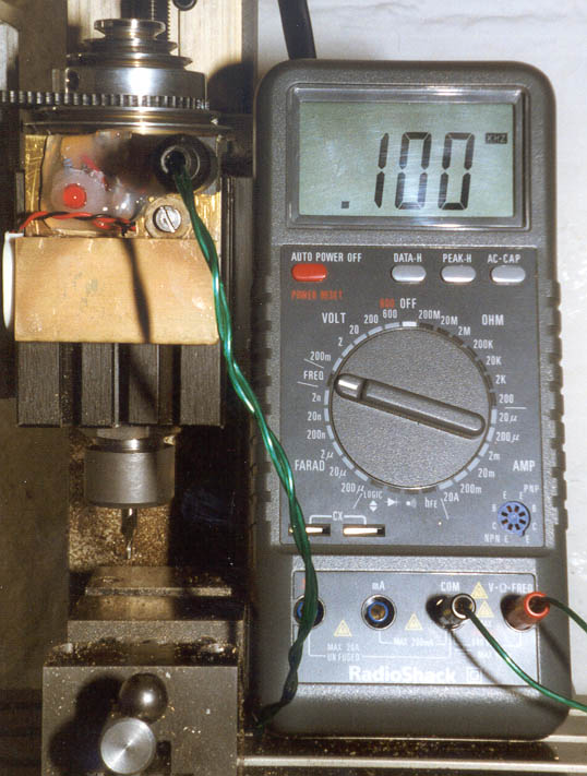
Photo 12: The digital sensor connected to a frequency measuring multimeter
It may be convenient to have some other means of determining and displaying the frequency of the pulse train, particularly as multi-meters tend to get used for other purposes as well as measuring spindle speeds, and some may regard them as an expensive solution to this problem. Various approaches are possible:
1. Develop a dedicated digital counting and display circuit. This is quite possible, and for those that are interested in following that route, the Maplin, Farnell and Electromail catalogues are a rich source of suitable components. The IC 7216A Universal Counter IC (RS stock number 307-941) is an example of an easy starting point for such a design. It has all the necessary counting and sampling circuitry built in, will directly drive an 8 digit seven segment display, and has settable sampling periods from 0.01 second to 10 seconds.
2. Make use of a digital to analogue converter (DAC) to generate a voltage or current output that can be continuously displayed on a voltmeter or ammeter. The 2917 Tachometer IC (RS stock number 302-047) is a suitable candidate. The 2917 device can take an input from a magnetic pickup (for example, RS stock number 304-166) held close to a toothed ferrous wheel attached to the shaft being measured; a gear wheel for example. The 2917 converts the pickup output into a DC voltage or current that can be displayed on a meter. It can also be adapted to take the output of an optical sensor such as the one described above.
3. RS components supply a complete ready-built digital tachometer board (RS stock number 440-509), with on-board mains power supply, that is based on the 2917 Tachometer IC. This can be set up to make use of a digital pulse train or the output of a magnetic pickup.
4. For those with a PC and experience of computer programming, an optical sensor can be interfaced to the parallel port of a PC, and a program written to count the number of pulses generated during a known time period. The result can then be displayed on the screen. This might be a suitable use for old PCs that are too slow to run modern power-hungry software packages.
Of these, the simplest and cheapest approach is likely to be the use of the Tachometer IC. I rapidly reached the conclusion that building a circuit around the universal counter IC would not be significantly cheaper than buying a digital multi-meter with frequency measurement capability, and would take a good deal of time. The digital tachometer board is likewise comparable in price to using a suitable digital multi-meter. I have experimented briefly with the tachometer IC, but have yet to spend sufficient time on it to report any useful conclusions, other than it shows signs of being a useful device. Having found the solutions that I have described above, using a DC motor and an analogue meter on the one hand and an infra-red sensor with a frequency measuring multi-meter on the other, it may be some while before I have any reason to take these other devices any further! For those that are interested in trying these devices, RS supply data sheets for the counter and tachometer ICs and for the tachometer board. These can be found in the relevant sections of their website, in the CD ROM version of their catalogue, or give them a call and they will mail copies to you.
Ref 1 Sherline tools and accessories can be obtained through Millhill Supplies, 66/68 The Street, Crowmarsh Gifford, Nr Wallingford, Oxon, OX10 8ES, UK.
Tel: 01491 838653
Website: http://www.sherline.com/
Ref 2 Taig Tools, 12419 E. Nightingale Lane, Chandler, Arizona 85249, USA. Tel: (602) 895-6978
Website: http://www.taigtools.com/.
Taig lathes and mills are also available from Peatol Machine Tools, 19 Knightlow Road, Harborne, Birmingham B17 89S, UK.
Tel/Fax: 0121 429 1015
Ref 3 This approach was the basis of an article and a design, originally published many years ago in "Science and Mechanics" (a US magazine). However, the article referred to the particular components of the kit that they supplied for their design, and did not describe how to calibrate the output for other motors.
Ref 4 Maplin Electronics Freepost SMU 94, PO Box 777, Rayleigh, Essex, SS6 8LU, U.K.
Tel: 01702 554000.
Website: http//:www.maplin.co.uk
Ref 5 Model Motors Direct, Hillside House, Baltonsborough, Nr Glastonbury, Somerset, BA6 8QJ, UK.
Tel: 01458 850061,
Fax: 01458 851048.
Ref 6 Farnell Electronic Components Limited, Canal Road, Leeds, LS12 2TU, U.K.
Tel: 0113 263 6311.
Website: http://www.farnell.com
Ref 7 RS Components (formerly Electromail): https://uk.rs-online.com/
Spindle and Surface Speed Measurement
© Tony Jeffree 2000
All Rights Reserved
Email me at this address...
website ({at}) jeffree.co.uk
Return to Model Engineering Activities page...