Introduction
I have a Taig CNC mill that underwent a previous upgrade, documented in an earlier issue of MEW, to replace the Z axis with the current specification "box" slide-way design and to upgrade the stepper motors to the current 200 oz-in torque versions; the however, for a while now I have been wanting to make some more far-reaching changes to the drive system of the mill. These changes affect two major aspects of how the drive system works:
- Improving the way that the motors couple to the leadscrew shafts;
- Upgrading the whole of the electronics and the control software to use a modern specification microstepping drive.
Once I had started work on the mechanical side, I realised that there will actually be very little difference between these upgrades and converting a new manual or "CNC-ready" Taig mill to CNC operation. So, while describing the upgrades, I will also include the additional information that would be needed to convert a manual mill to CNC.
This article is part 1 of a series of articles that I plan to write over the next few months (years?) as I work on various aspects of the conversion. The second part deals with replacing the motors and electronics with a new microstepping drive system. The third part will look at the PC and software elements that will complete the system. As the writing of these articles will necessarily go hand-in-hand with my working on the conversion itself, I cannot offer any guarantees as to exactly when parts 2 and 3 will emerge in the magazine; suffice it to say that I will write therest of the series as soon as I can.
For those readers that have a Taig CNC mill and are happy with the way their PC/software/drive electronics are working, the mechanical changes described in this article offer an easy way to improve the way their system works without getting into the more complex aspects of electronics and software; from beginning to end, the changes described here took me a couple of (short) evenings of workshop time.
Of course, if you ignore the Taig-specific aspects of this series of articles, the rest of the conversion will potentially be applicable to other mills of comparable size - for example, the Seig X1 mill that is available from the various UK machine importers.
Motor mounts and couplings
The standard Taig motor mounting arrangement can be seen in Photo 1. This is basically a length of Aluminium tube that screws onto the threads on the outside of the leadscrew bearing housing (see Photo 2 which shows the Z axis housing with the mount removed), with a captive rectangular mounting plate drilled and tapped to match the hole centres on a standard NEMA 23 frame size stepper motor. These mounting tubes can be obtained from Taig in the USA or Peatol in Europe; however, I have also included drawings of the mount components for those that fancy making their own (see Figure 1) - the drawings are pretty self-explanatory so I don't plan to go into a blow-by-blow description of how you would make them.
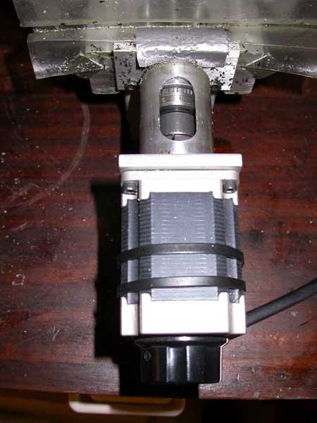
Photo 1: Taig motor mount
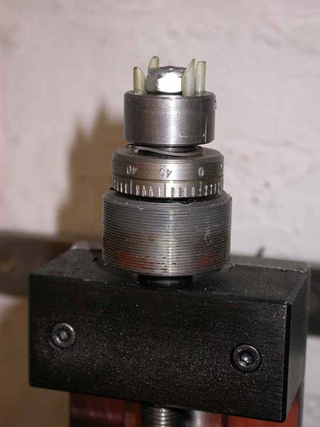
Photo 2: Taig motor coupling - Leadscrew half
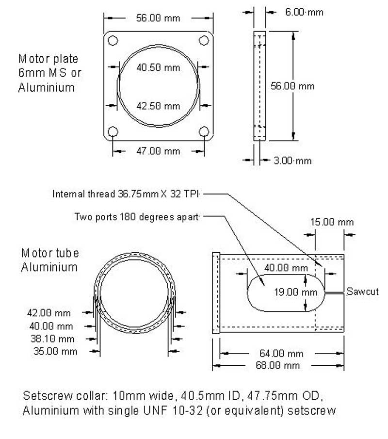
Figure 1: Motor mounting tube and plate
The threaded end of the tube is split with a couple of saw cuts, and a setscrew collar is used to clamp it in position once the tube has been screwed onto the housing. On my original mill, the setscrew collar fixing method wasn't used; the tubes were simply thread locked in position, so dismantling the mounts for this exercise involved careful application of a blowtorch to soften the thread locking compound to allow the tube to unscrew.
Photo 2 shows the leadscrew shaft "half" of the motor coupling and the means of adjusting bearing end float. At the bottom, next to the bearing housing is an adjustable indicator dial, engraved in thou as this is a 20 TPI leadscrew Imperial machine. Not visible in the photo, there is a small circlip on the shaft under the indicator dial (but more of that later). Above that is one half of the motor coupling, which is axially drilled to take the four 1/8" diameter plastic quills that can be seen in the photo; these locate in matching holes in the motor half of the coupling that can be seen attached to the motor shaft in Photo 3. The indicator dial and the leadscrew half of the coupling both have a keyway machined into their bore, and share the use of a single Woodruff key that serves to locate them and couple the drive boss to the leadscrew. The UNF 5/16 nut on the end of the leadscrew tightens the coupling boss and the fixed central boss of the indicator dial down onto the circlip mentioned earlier; I presume that the purpose of the circlip is therefore to prevent over-tightening affecting the smooth running of the back-to-back ball races that are contained in the bearing housing. On earlier machines, this is a half nut held in place with thread locking compound; on later machines this is a Nylock nut.
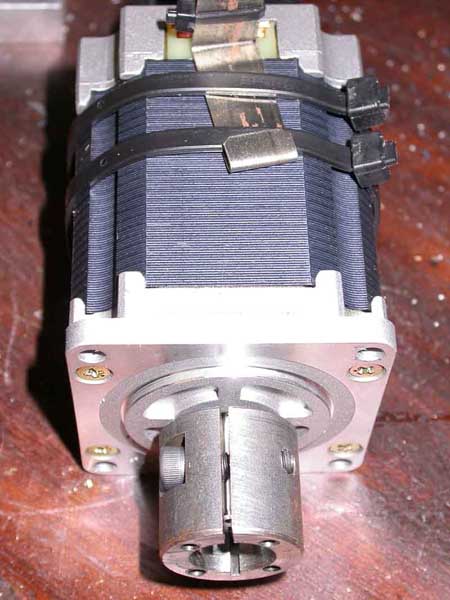
Photo 3: Taig motor coupling - Motor half
This drive arrangement was the target for the mechanical changes in this project, for the following reasons:
- The quality of the coupling between the motor and the leadscrew, and in particular, control, of backlash in the coupling, depends upon the accuracy and stiffness of the four plastic quills that join the two drive bosses. When new, these work reasonably well, and don't introduce significant backlash; however, at least on my machine, I have found that they wear over time and the backlash noticeably increases.
- As mentioned above, the Woodruff key in the leadscrew shaft serves to couple the drive boss to the leadscrew. Any play between the key slot in the shaft, the key itself, and the keyway in the boss can show up as backlash in the drive to the shaft. Although this can be controlled to some extent by tightening the nut, this is unsatisfactory (at least, it was on my machine!), as on one of my mill axes, applying sufficient torque on the nut to lock up the drive boss can also lock up the ball races. On another of my mill axes, the positioning of this circlip means that although you can tighten it up enough to hold the drive boss in place, it is not possible to adjust the end float/pre-load on the ball races. In either case, the arrangement is unsatisfactory from the backlash point of view.
- The plastic quills can be a pain to line up properly when removing/re-fitting the motors. While this isn't something that you need to do frequently with a properly adjusted machine, it is irritating on those occasions when it is necessary.
In the various other CNC activities I have been involved in, I have found that Oldham couplings (see Photo 4) provide a very satisfactory, and backlash-free, method for coupling shafts together, so the modifications I describe allow Oldham couplings to be substituted for the cruder Taig couplings. In the process, the drive to the leadscrew no longer relies on (or even requires the presence of) the Woodruff key, and end float can be adjusted without involving the drive coupling hardware.
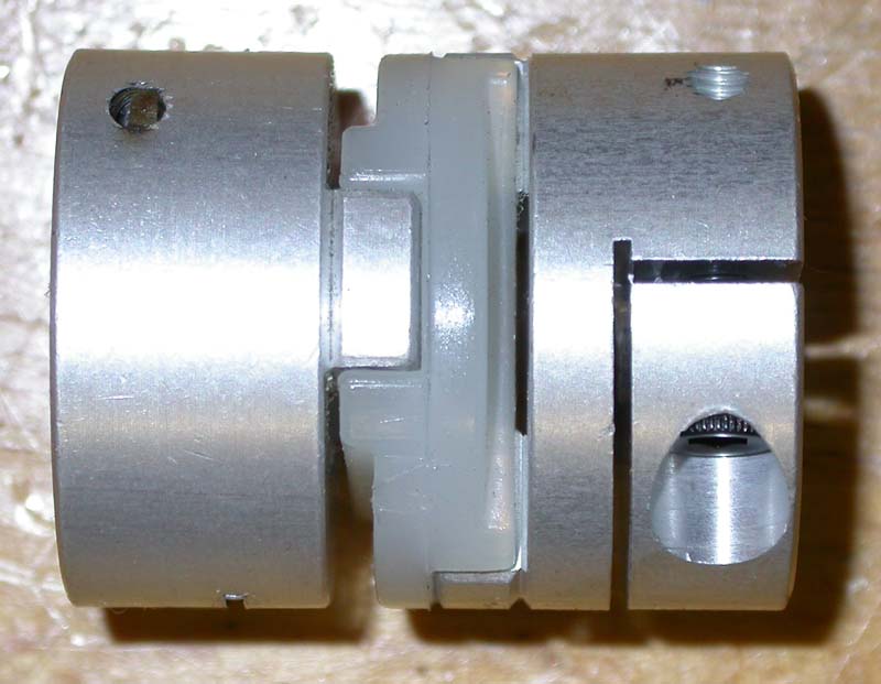
Photo 4: Oldham coupling
Leadscrew modifications
The Oldham couplings that I use are 25mm diameter and each of the hubs is 12mm thick, which is near enough the same size as the coupling components supplied by Taig. However, as a plastic torque plate is used to join the coupling bosses together, the nut on the end of the leadscrew needs to be moved to the other side of the coupling boss.
If you are starting with a manual Taig mill (as opposed to modifying a Taig CNC mill), then you will find that the crank handles take the place of the coupling boss in Photo 2; otherwise the arrangement should be the same as described above.
So, what needs to be done is to machine the ends of the leadscrews down to ¼" diameter, for a length of 12mm, to take a ¼" bore 25mm diameter Oldham coupling hub, and to cut a 5/16" UNF thread from the shoulder formed by this machining operation, for a length sufficient that the nut will do its job of tightening down onto the hub of the indicator dial and in turn, adjusting the shaft end float and bearing pre-load.
The first step is obviously to dismantle each of the three leadscrews. In the case of the CNC mill, remove the stepper motors by unscrewing their mounting screws, and unclamp and unscrew the motor mounting tube from the bearing housings. With either a manual or a CNC mill, you now remove the two cap screws holding the bearing plates onto the ends of the axes. The leadscrews can now be unscrewed from their feed nuts and the complete leadscrew/bearing housing assemblies removed from the mill. Undoing the nut on the end of a leadscrew allows the engraved dial, and either the coupling boss or the hand crank lever, to be removed from the end of the shaft; the Woodruff key and the small circlip can also be removed, and the leadscrew will now slide out of the bearings.
The screw is then held in a 3-jaw chuck with the machined end of the shaft protruding from the jaws. I used some Brass shim stock to protect the screw from damage during this operation. I also supported the free end of the shaft with a 3-point steady while machining was in progress.
Once the ¼" diameter has been formed, the thread for the nut can be cut; if you don't have a suitable UNF die, a substitute is perfectly acceptable - 5/16" BSF for example, or maybe even M8 as 5/16" is 7.9375". Photo 5 shows a "Before and After" - the upper shaft in the photo is the original leadscrew end; the lower shaft shows the result of the re-machining.
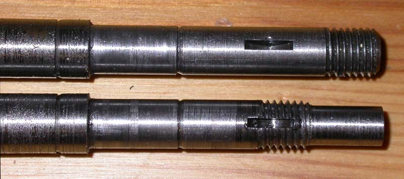
Photo 5: Re-machining the leascrew ends
The leadscrew end is then fed back into the bearing housing, the indicator dial fitted in place (without the Woodruff key), and the nut screwed into place, using a drop of thread locker so that it will stay put if you don't have Nylock nuts. The nut should be adjusted so that there is no end float in the shaft, but not so tight that the smooth operation of the ball-races is affected.
An Oldham coupling hub is then attached to the end of the shaft. The split clamp-type hubs are best for this application; there are versions with paired setscrews, but for these you need to file flats on the shaft. RS stock a wide range of these couplings with different bore diameters. The ¼" bore clamp-style hub is stock number 748-055; two will be needed for each axis (one for the motor, one for the leadscrew). Stock number 748-156 is the matching torque plate; unfortunately the latter only come in packs of 10. If you don't need more than the three needed for this conversion, contact L.S. Caine Electronics who will sell these components in smaller quantities. The standard NEMA 23 motor shaft is ¼" diameter; however, some motors these days have different shaft diameters - I have used 6mm, 8mm, and 10mm diameter stepper motors, so best check what diameter the shafts are before ordering the Oldham hubs. The ¼" diameter hubs can be bored out for larger shaft diameters; RS also stock them in larger sizes.
Feed nuts
The standard feed nuts on the manual mills, and on the earlier CNC mills, were plain Brass or Bronze nuts with no adjustment for wear; later CNC mills had nuts that allowed adjustment to take up wear (a longitudinal slit along the nut and a clamping screw that allowed the nut diameter to be reduced). These adjustable nuts can be obtained from Taig in the USA or Peatol in the UK if you want to further reduce the leadscrew backlash. If you plan to fit these nuts it is worthwhile to take some time while the mill is disassembled to adjust the clamping screws for minimum backlash on the leadscrews. Obviously, as any wear on the leadscrew is going to be in the middle of the range of travel, this is going to be a compromise between backlash reduction in the middle and freedom of movement at the ends.
Re-assembling the axes
This is a simple reversal of the disassembly process. The screw is fed back into the feed nut, and the bearing housing mounting plate is re-attached to the end of the axis - see Photo 6.
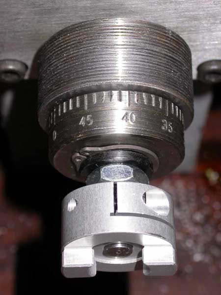
Photo 6: Leadscrew bearing reassembled
The motor mount components (see Photo 7 and Figure 1) can then be fitted, remembering to fit the motor plate over the tube first, then the setscrew collar, before threading the tube onto the bearing housing. You will need to fit the motor half of the Oldham coupling, and the torque plate, to the end of the motor shaft and do a trial fitting of the motor, in order to determine how far the tube needs to be threaded onto the bearing housing. The aim is for there to be no end play at all between the torque plate and the two coupling bosses; however, avoid any axial force on the motor shaft, and the cut-outs in the tubes should end up at the top and bottom, so the dials will be visible and swarf can fall through. If necessary, the Oldham hub positions can be adjusted on their shafts to make this work - their clamp screws should be accessible through the ports in the mounting tubes. It is also worth bearing in mind that although the NEMA 23 standard calls for a standard shaft length, some of the ones I have seen with non-standard shaft diameters also have longer-than-standard shafts. With these, the ultimate adjustment option (application of hacksaw-and-file) may be required. Photo 8 shows the Y axis fully re-assembled, with the motor attached to the mount.
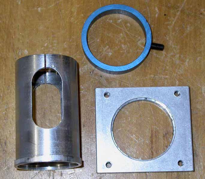
Photo 7: Motor mount components
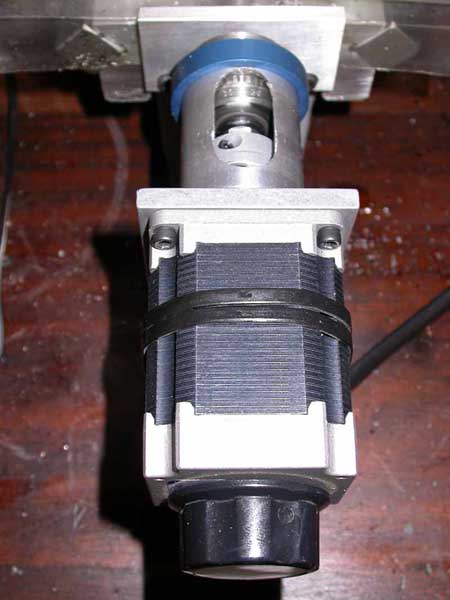
Photo 8: Y-axis completely reassembled
Results
Testing the mechanical improvements out using the original Taig motors and half-stepping drive system (each half-step equating to 1/8th of a thou) shows that the backlash in the axes has improved dramatically - from something in the region of 3-5 thou on each axis before the mechanical re-work, to a situation now where, using a dial indicator to measure movement of the table, I cannot measure any backlash at all as, if there is any there to measure, it is smaller than the mechanical resolution of the drive system (i.e., less than 1/8th of a thou). I think that I can therefore safely say that this was a successful exercise.
Suppliers and other contact details:
1. RS Components. Tel: 01536 201201 Website: https://uk.rs-online.com/
2. Model Engineers Digital Workshop is no longer trading.
3. Peatol Machine Tools, Website: http://www.peatol.com
4. Taig Tools, 12419 E. Nightingale Lane, Chandler AZ 85249, USA. Tel: +1 480 895 6978, Website: http://www.taigtools.com