Photo 1 - Extended tailstock lever
Copyright © Tony Jeffree, 5th February 2002. All rights reserved.
I have used a Taig lathe for several years now, and for most of that time, have been meaning to make some improvements to the tailstock to increase its ease of use and versatility. There were three things I wanted to do:
1. Extend the tailstock lever and make it more comfortable to use (the standard lever is an unadorned strip of ½" X 1/8" mild steel);
2. Replace the adjusting/locking screws (normally UNF 10-32 cap head screws) with levers or knurled knobs, to avoid the constant search for the right size of Allen key; and
3. Provide a means of accurately adjusting the offset of the tailstock, for taper turning or to re-set it on-axis after taper turning.
I recently made some time to do something about these planned improvements, and this short article describes how I went about them.
The standard tailstock lever is serviceable, but can be on the short side for drilling larger holes. It can also be rather uncomfortable to use, as it is basically just a length of 1/2" X 1/8" steel strip, with square corners that can dig into the hand. Extending the lever to about twice its length, and at the same time, giving it a more comfortable handle, improves the usability of the tailstock considerably for drilling operations.
Photo 1 shows an example of how this can be achieved-it took about half an hour to make this handle, using some materials from the scrap box. The outer portion of the handle was made from a 6" length of 15mm OD copper plumbing pipe; a blanking cap (also a standard plumbing fitment) soldered on one end nicely finishes off the free end of the handle. The inside diameter of this pipe is a little larger than the 1/2" width of the tailstock lever, so I cut a 2" length of 1/2" diameter brass rod, and cut a 1.5" long, 1/8" wide, axial slot in the rod to accept the lever. This slotted brass rod was then soft soldered it into the open end of the tube, leaving the slotted end flush with the end of the tube.
Photo 1 - Extended tailstock lever
Cutting the slot can be achieved with care by using a hacksaw; make two longitudinal cuts straddling the axis of the rod, and then cross-cut at the base of the cuts with a piercing saw to take out the sliver of brass that is left between the two long cuts.
The handle is then fitted onto the tailstock lever, and two holes drilled for fixing screws. These holes should first be drilled right through the tube, brass insert, and lever, using a suitable tapping drill-I used 4BA screws, and a 3.1mm tapping drill. Then the holes are opened out through the first wall of the tube, the first half of the insert, and the lever, leaving the hole through the second half of the insert and the second tube wall still at tapping diameter. The hole is then tapped and the screws fitted. Tightening the screws therefore has the effect of clamping the new handle onto the existing lever.
Having made this modification, the leverage obtainable with the tailstock is considerably increased; do not be tempted to apply more force to the lever than is appropriate for the machining operation being performed, as damage to the lathe and the workpiece may result. If you find, for example, that a drill being fed from the tailstock isn't cutting terribly well, maybe the real reason is that the drill isn't very sharp! Of course, as the handle is made from copper tube, there is a natural limit to the force that can be applied before the tube bends, which is probably just as well.
Replacing the cap screws on the tailstock (one that locks the tailstock to the carriage, one that locks the set-over adjustment slide, and one that locks the tailstock ram) with knurled knobs is a straightforward job. The screws are UNF 10-32 and about 1" long, and replacements can be turned from 5/16" mild steel round stock. The overall length of the replacement screw should be about 1.75"; turn down a 1" length of the stock to the right diameter for threading 10-32 (0.19") and thread it using a UNF 10-32 die. I find that threading small screws like this is easily done in the lathe, using a 1/2" chuck in the tailstock pushed up against the back of a hand die holder to keep it square, and turning the lathe chuck by hand. Of course, if you have invested in a tailstock die holder, this operation can be even easier!
The full length of the screw will need to be threaded. The screw can then be parted off from the parent stock, leaving a 3/4" length of 5/16" diameter material as the "head" of the screw. A knob can then be fashioned from round bar of a suitable diameter—ideally about 1.25" diameter—bored 5/16" for the screw head, and parted off to 1/2" thick after knurling the outer surface to improve grip. The screw is then Superglued into the hole in the knob after cleaning off any surface oils and swarf. The result can be seen in Photo 2, which shows two such knobs fitted to the tailstock.
Photo 2 - Replacement locking knobs
The tailstock can be adjusted for taper turning, by releasing the pinch bolt at the back of the headstock and sliding the tailstock body over by the desired amount before re-tightening. If taper turning using tailstock offset is something that you are likely to want to do fairly often, it is useful to be able to offset the tailstock by controlled amounts, and to be able to return the tailstock to the lathe axis reasonably quickly when the taper turning is complete.
Photo 3 shows a modification to the tailstock to achieve this end. The micrometer adjuster is rather similar in construction to the handwheel and leadscrew that advances the lathe cross-slide; both use a 1/4" 20 TPI leadscrew and a handwheel with 50 graduations, giving adjustment in thousandths of an inch. Photo 4 shows the "lead nut" fitted at the back of the tailstock - a 3/8" thick steel plate that is attached to the base of the tailstock with a pair of socket head UNF 10-32 screws. In the prototype, I chose to use countersunk screws threaded into the base itself; a slightly easier option is to use the T-slots provided on the rear of the tailstock base, and this is the approach used in the following description.
Photo 3 - Micrometer set-over adjuster
Photo 4 - Micrometer lead nut at rear of tailstock
The photo of the handwheel shows a hole where a handle was originally fitted; however, as this fouled the extended tailstock lever, and proved to be unnecessary anyway, I removed it; hence, this does not feature in the description below.
Figure 1 shows the main parts involved in making the adjuster. The handwheel is cut from 1" diameter material - brass, aluminium or steel, as you see fit. The first job is to face off the stock and bore the 1/2" diameter recess in the face of the handwheel, and give a slight radius to the edge of the wheel. The tapping hole for the 1/8" BSW thread is then drilled and tapped. The handwheel can then be parted off to 3/8" thick. I engraved my handwheel with 50 graduations (one thou movement per graduation) using my CNC mill; for those without this very useful facility, engraving the graduations will involve some other means of indexing, such as a dividing head or rotary table, or an index plate attached to the lathe headstock.
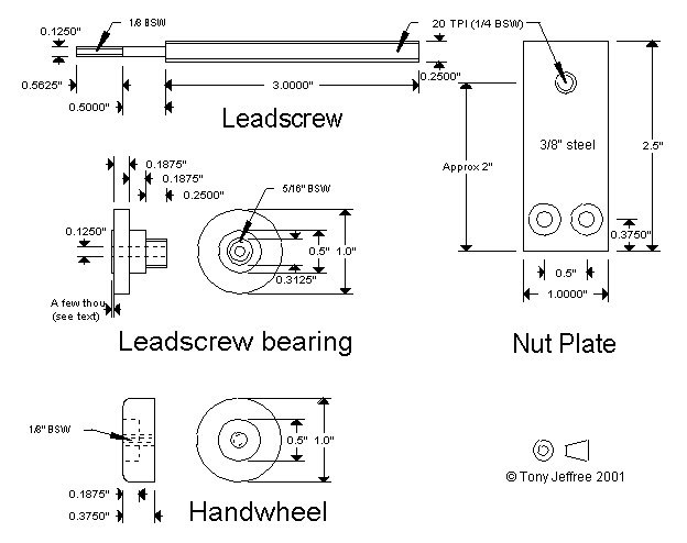
Figure 1 - Micrometer adjuster components
The leadscrew bearing is also cut from 1" diameter stock; again, the choice of material is not critical. This is faced off, drilled and reamed 1/8", and the two large steps shown in the diagram are machined. The first reduces the diameter to 5/16" over a length of 1/4", which is subsequently threaded 5/16" BSW; this thread will be used to lock the bearing into the body of the tailstock. The diameter of the second step is not critical. The bearing can then be parted off from the parent stock, and reversed in the chuck to true up the face. Note that the central 1/2" diameter of this face protrudes a few thou; this forms the bearing surface that the handwheel will bear against.
The leadscrew itself is cut from a length of 1/4" 20 TPI threaded rod. This can be held in the 3-jaw chuck to machine down to 1/8" diameter and thread the last 1/2" or so 1/8" BSW to match the handwheel. You will also need a small jam nut tapped 1/8" BSW; I made a domed nut from a 1/4" length of 1/4" diameter brass rod, with two flats filed on it.
The leadscrew and bearing assembly can now be assembled. The thin end of the leadscrew fits through the thin end of the bearing block, and screws into the back (non-recessed) face of the handwheel. This should be adjusted for minimum play consistent with the bearing still being able to rotate. The jam nut is then threaded in place with a drop of Locktite threadlocker, and tightened to lock the handwheel onto the leadscrew.
The next step is to cross-drill the tailstock body with a 5/16" BSW tapping drill. The hole passes right the way through the tailstock, in the middle of the thinnest part of the tailstock body; this is approximately 2" above the bottom of the complete tailstock assembly. The near end of this hole can then be tapped 5/16" BSW to take the leadscrew bearing.
The last item to make is the nut plate. This should be fairly substantial - I used 3/8" mild steel, and the diagram is fairly self-explanatory. The plate should be held in place with its T-bolts so that the position of the 1/4" 20 TPI can be spotted through from the hole in the tailstock body; the hole is then drilled and tapped.
Finally, the leadscrew assembly is screwed into the tailstock body, again using a drop of Locktite to lock the threads, and the leadscrew threaded into the nut plate.
Setting the tailstock on-axis, or to a desired offset, is made much simpler and quicker with this device. For "quick-and-dirty" adjusting, where high accuracy is not required, for example, when drilling from the tailstock, proceed as follows. A piece of soft material (brass or aluminium) is held in the three-jaw chuck and faced off. The tailstock is brought up to the chuck, locked in position, and the tip of the ram used to carefully score a circle on the end of the cleaned up face of the soft metal. Do this by turning the chuck by hand, rather than under power. The radius of the scored circle (easily measured with a calliper or dividers) gives the distance that the tailstock is offset from the lathe axis; this can be quickly "dialled in" on the handwheel. Obviously, with more sophisticated measurement techniques (for example, a dial gauge held in the lathe spindle, indicating against the circumference of the ram) the micrometer adjustment can be used to centre the tailstock with a higher degree of accuracy.
Improvements to the Taig tailstock
© Tony Jeffree 2002
All Rights Reserved
Email me at this address...
website ({at}) jeffree.co.uk
Return to Model Engineering Activities page...