Introduction
I have wanted a “proper” tool & cutter grinder for some while, and decided fairly early on in the selection process that the Worden would most likely fit the bill for a number of reasons:
- Firstly, it is available in kit form, with many of the components already prefabricated from sheet steel and just requiring finishing, so it seemed like the easiest option construction-wise – having spent the last few years building tools and doing CNC conversions on machines, I didn’t want another lengthy tool construction project that would further delay the time when I can actually use all the stuff I have made to make something that isn’t another tool.
- Secondly, although there may be other designs that are more capable and versatile than the Worden, I felt that the Worden would do all that I need it to do and more, which is basically sharpening lathe tools, drills, and engraving cutters, maybe making form tools, and possibly touching up the ends of end mills if I feel really adventurous.
- Thirdly, it seemed to me that the inherent simplicity of setup with the Worden would mean that I would actually use it for said purposes, rather than allowing it to gather dust under a bench.
- Finally, and most importantly, it isn’t a Quorn.
I can already feel the hackles rising and hear the knives being honed to a razor’s edge as the MEW readership, Quorn chapter, attempts to digest that final sentence, and start muttering “did he really say that?” under their collective breath, so I feel I must explain this comment as I hastily don the protective Kevlar vest. To some readers, I’m sure what I say will be heresy; to others, the point will be all too clear.
Building a Quorn seems to have become a kind of Holy Grail in the model engineering community – a necessary step en route to becoming a proper grown-up Model Engineer (capitals intended); a kind of Rite Of Passage or Membership Badge that many aspire to, but that all too few actually manage to pin on their lapels. The Quorn is undoubtedly a very versatile machine, especially if all of the attachments, bells and whistles are built, rung, and blown respectively. However, it is by all accounts a shed load of work to build one, and even more work to build one well, and there are plenty of traps for the unwary en route; cutting the much fabled 1 TPI thread being but one example, not to mention having to corner the world’s entire annual production of ball handles. And when you have finally finished building it, setting the thing up for use is, I am reliably informed by friends I know that have owned and used one in the past, a time consuming, fiddly, and therefore ultimately unrewarding process.
Hence, while there are probably a very large number of Quorn casting kits that have been sold over the years, and many, many more copies sold of the worthy Professor’s iconic tomes on its construction and use, my guess is that the vast majority of those castings and books have been looked at and/or read just once before being consigned to some quiet corner of the workshop to gather dust. Some owners may even have figured out that the castings can be reconfigured to make a great little doorstop, or maybe an anchor for a small rowing boat – just perfect for those fishing trips at the weekend – even better if you take the Professor’s books with you to read while you wait for that elusive nibble.
Of the casting kits that have actually made it into the light of day as completed Quorns, I would wager that a good number will be gathering dust too, because more often than not, the owners will find it quicker and easier to sharpen their stuff some other way, or like me, will take the easy way out and go for indexable carbide tooling and “disposable” end mills. So, for many, the real rite of passage has become the ability to claim to your peers that you have started to build a Quorn, and of course you can back up the claim because you have bought the book and/or acquired a set of castings that are gathering dust under your bench, much as someone that once leafed through a brochure for a day trip to the foothills of the Himalayas might claim to have started their ascent of Everest. You can almost imagine the hushed conversations during tea break down at the local model engineering club – “I’ve just started building a Quorn” whispers George, conspiratorially, dunking his Rich Tea into his cup of very, very rich tea. “Neither have I” replies Arthur, and they both nod sagely and take a contemplative slurp at the Tetley’s while moving briskly on to a safer topic of conversation. Of course, George and Arthur are both painfully aware that the Quorn conversation had to end there, otherwise they would have to admit to each other that in reality it will be a cold day in Hell before work on their Quorn has really started, let alone resulted in a usable machine. So, actually talking about the Quorn you are building has become a sort of model engineering equivalent of the Cold War theory of “Mutually Assured Destruction” – neither party wants to get too deep into the conversation because neither of them want their ME street cred to be blown to smithereens.
I exaggerate of course…don’t I?
Anyhow, I digress. While chatting with Kirk Burwell of Hemmingway Kits at the Harrogate show in 2009 (or was it 2008? Yes, I’m afraid my Worden kit has done its fair share of dust gathering too!), I finally decided pony up some hard-earned cash and purchase a Worden kit, taking advantage of the show offer of a free add-on, for which I chose the four-facet drill grinding adapter kit as this would meet one of my primary reasons for having the machine in the first place. It would also allow me to get rid of the Drill Doctor that has also been gathering dust on my bench, because while it is undoubtedly easy to use, my experience has been that it is, at the same time, impossibly difficult to use if your objective is to produce a decently sharp and symmetrical drill point.
The Kit
The kit duly arrived – a large and very heavy box full of pressed and punched steel components, various lengths of bar stock, a motor, and various other electrical components – and I struggled with it down the narrow stairs to the cellar. First job – unpack it all and read the instructions. Photo 1 shows the components unpacked on the bench:
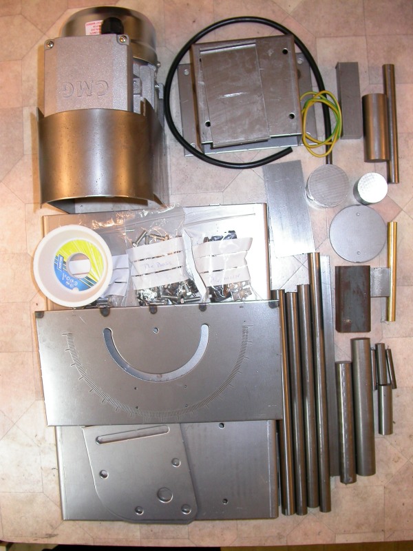
Photo 1
All seemed very straightforward; however, the instructions provided are clearly deficient in what is by far the most important aspect of building any new machine tool – how are you going to paint it, and in what colour? Should it be Myford not-quite-battleship grey, or Myford not-quite-British Racing Green, or Myford – err…what do you call their latest colour…? Mediterranean-on-a-bad-day Turquoise? Or maybe Warco not-quite-Myford green, or Chester off-white, or Arc Eurotrade “My other car is a Ferrari” Red? Hammerite hammered finish or Hammerite smooth? Leaded paint or unleaded? I felt a trip to the DIY shop coming on – and no, not That DIY Shop – the DIY superstore for existentialists with time on their hands, “Be and Queue” – no, we are actually blessed with two real DIY shops in my home town, ones that have real counters with real tills that have real mechanical bells that ring when the cash drawer opens, with no electronic barcode scanners, and no self-service checkouts and no disembodied female voices telling you to “Please Scan The Barcode”, with real dusty boxes on the shelves, containing terribly useful things that you might actually need, that might actually do the job they were designed for, and that you might actually want to buy some day, where you are served by real dusty old guys with bad attitudes that don’t know how to operate the credit card machine, and wrap things for you in real brown paper bags with real holes in the bottom. I wander into the larger of these wonderful DIY emporia. “Have you any spray cans of Hammerite smooth?” I ask, in mild trepidation, to the not-very-cheerful gent in the flat cap and brown storeman’s coat with the forest of pencils behind his ear, who is chewing his way through his second 6” wire nail of the morning and washing it down with a cup of neat paint stripper. He rummaged under the counter. “Harrumph…there was some ‘ere somewhere…<spit…ding>…’ere’s a couple of cans of red…any good?” He slams the cans down on the counter top as if to challenge me to ask him for something he can’t find. “Err…any other colours?” I ask, trying to avoid eye contact. “Nah.” I feel that the reduction in the number of syllables may be a bad sign. “Nothing out the back in the store room?” I ask. Pushing my luck here, but I hold my ground. Definitely no eye contact now. “You’ll ‘ave to ‘ave red-and-loike-it” he grunts, “Only mumble-mumble pounds each.” I capitulate, not daring to ask him to repeat the price. “Cheap at half the price” I mutter darkly as I hand over some cash. He hands me the change and wanders out the back to bite the head off a whippet, while I exit the shop with my cans of Hammerite red-and-loike-it. Not a bad red actually, and from previous uses, Hammerite smooth works well – I tend to avoid the hammered finish version because it just ends up looking cheap & nasty. Now I did, just for a brief moment, consider having the parts chrome plated instead of painting them, but I concluded that that would have been a tad over the top, not to say expensive; however, you may know different!
De-burring
Figure 1 shows the overall layout of the machine, Figure 2 the work-slide, and Figure 3 the wheel mounting hub, with tables showing the materials used for the various components. In the remainder of the article, numbers in brackets refer to the component numbering scheme used on these figures.
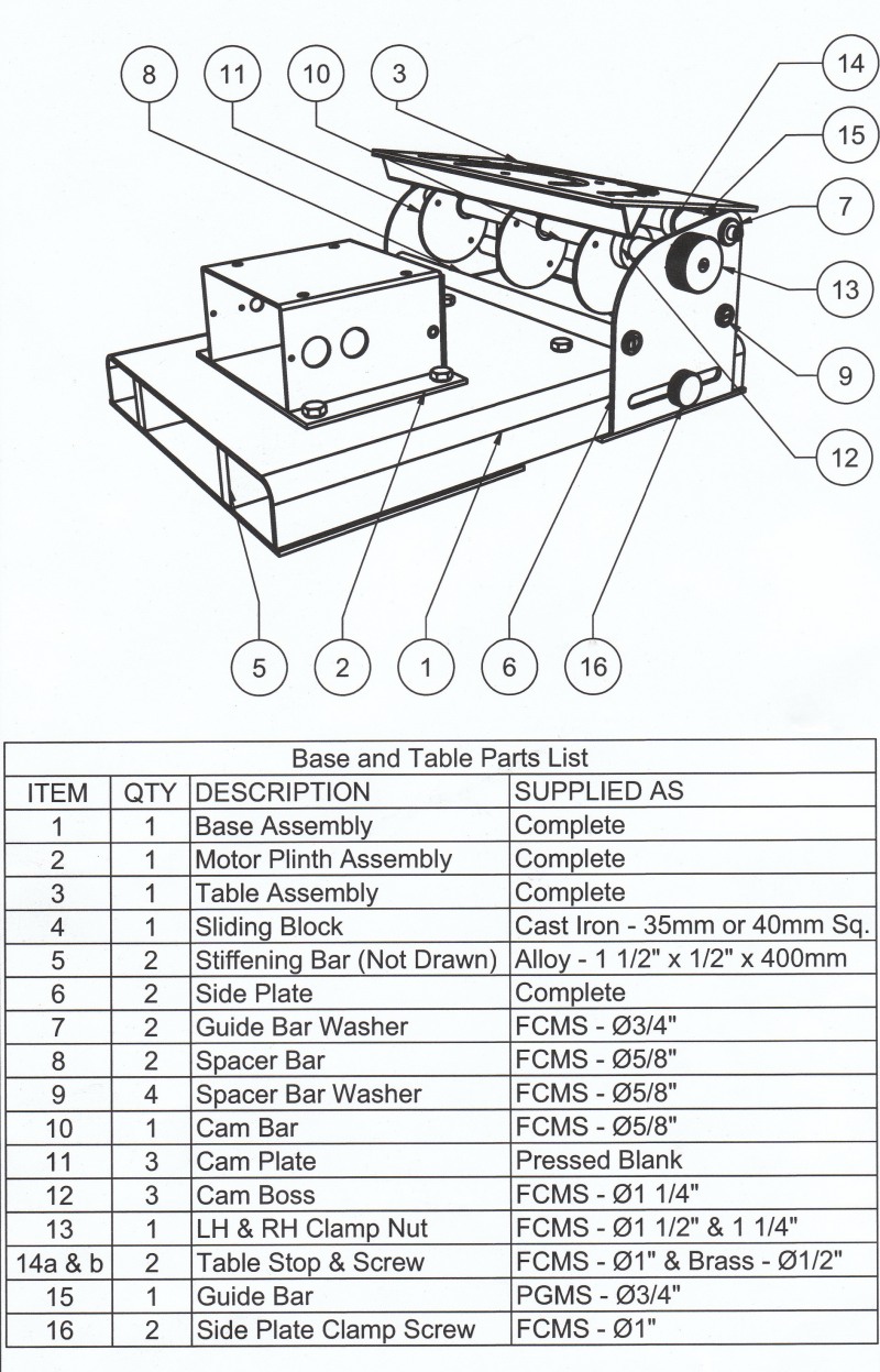
Figure 1
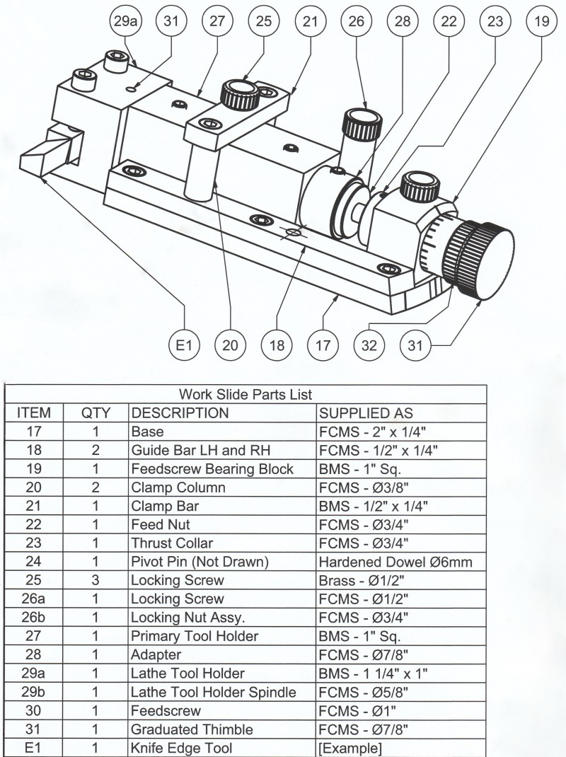
Figure 2
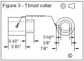
Figure 3
The first job, after deciding on the colour scheme of course, is to de-burr the sheet metal parts (1, 2, 3, and 6). I have to say that Kirk Burwell’s surname proves to be particularly appropriate – he (or more accurately, the CNC punch-and-fold company that Hemmingway uses) does indeed burr these parts very well. Photo 2 gives you an idea of what you will have to deal with here; the punch and fold machine cuts out the arcs by nibbling away at them with a large number of small radiused cuts, so the result is a scalloped edge that needs a fair bit of elbow grease to get smooth.
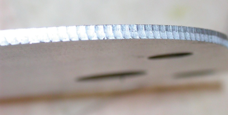
Photo 2
Memo to Kirk: Have you considered switching to CNC laser cut plates instead of CNC punch-and-fold? The finishing would be so much easier.
The instructions that come with the kit suggest that “all edges should be draw filed to get rid of sharp edges left by the punches, rounding all corners”. A much quicker approach is to use a belt or disc sander for the external edges, if you have one to hand, and a Dremel-style electric hand drill fitted with a small mounted stone for the radial slot in the table (3) and the long slots in the side plates (6), although the mounted stone I used didn’t survive the experience all that well (see Photo 3).
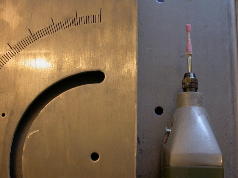
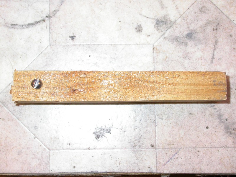
Photo 4
Doing the numbers
The next job was to number-punch the table to give 90-0-90 degree markings. The instructions suggest a 4mm punch set; the set I had to hand was only 2mm, so I decided to make do, although I have to admit the resultant numbers would benefit from an increase in size. A simple radial arm made from a scrap of wood with a small round-head screw in one end (Photo 4) is helpful as a means of ensuring that the numbers are properly placed; the screw head locates in the centre hole on the table, and the arm length is chosen so that when a punch is held against its square end it is in the right position for punching the number. You could of course make the deluxe version of this jig, with a slot in the end to make sure the punch is vertical in both axes, but the version shown worked for me. Despite my previous bad experiences with hand punches, which seem to magically generate the wrong numbers despite careful visual inspection before use, I did actually manage to punch all of the right numbers in the right positions, and the right way round, oriented to be read from the operator’s position (i.e., the tops of the numbers towards the centre of the circle).
The instructions suggest leaving off the 90 degree marks as the table is difficult to support at the extreme ends because of the rubbing strip that is mounted underneath; however, in practice I found that punching the 90 degree marks was not a problem either.
Memo to Kirk: A laser etched scale would be a great improvement on the current design – it would be a trivial addition to have the numbers laser etched as well as the degree marks, which would give a much neater finish than using hand punches.
The base unit
This is mostly pre-fabricated for you; it consists of a flat plate with a U-section plate spot welded on top to form a flat rectangular box with two open ends (1), one at the motor end and one at the operator end of the finished machine. Two longitudinal aluminium stiffening bars (5), are bolted in place from top and bottom through pre-punched holes in the plates to provide stiffening, although given the gauge of the steel plate used, it isn’t clear to me that the stiffening is really required. Assembly is a matter of spotting through the plates onto the Ally bars and drilling/tapping M6 for the retaining bolts and washers. It is worth not getting too blasé about the tapping process – the aluminium provided is of the soft and sticky variety that is notoriously good at eating taps if you don’t treat it right – plenty of tapping fluid and not too much enthusiasm with the wrench is the way forward here. Suffice it to say that my collection of M6 taps is now one fewer than it was when I started, and one of the M6 bolts provided is now surplus to requirements…
The base unit has 3 M6 captive nuts that have been inserted by the punch-and-fold machine. I found that all three had been slightly squashed in the manufacturing process, so they needed a quick run through with a M6 tap to clean up the threads before they would accept an M6 screw.
Painting the sheet steel bits
You can, of course, leave the machine unpainted; however, I feel that a paint finish is desirable to protect from rust and also to improve the appearance of the finished machine. If you are going to paint yours, then it is worth doing it early in the process; the paint will (slightly) change the dimensions of the base (1) and the two sheet steel side plates (6) that support the tilting table, and therefore change the dimensions needed for the ¾” ground steel Guide Bar (15) and the smaller Spacer Bars (8) and Cam Bar (10). Before painting, it is worth heeding the instructions on the can that suggest all smooth surfaces should be abraded; the paint seems to need a key to adhere well, and will flake off easily otherwise. You will probably find that getting good coverage on all of the surfaces that need painting (the top surface of the work table should be left unpainted) will take most of 2 spray cans of Hammerite Smooth (or 3 cans in my case, as one of them ran out of propellant after only a few squirts of paint). Once painted, these parts can be happily left to one side to give the paint a chance to set really hard, which takes a considerable time with Hammerite.
Machining the sliding block
The work table of the Worden is carried on an 80mm long cast iron Sliding Block (4), bored for a sliding fit on a ¾” diameter ground steel Guide Bar (15).
The above description neatly illustrates one of the intriguing features of this kit – it manages to mix and match all the common units of measurement used in model engineering in a single project, and often on the same part. We have a mixture of metric and Imperial linear dimensions, metric and Imperial screw sizes/pitches, and even a few BA thread sizes thrown in for good measure. I’m pretty sure I spotted a furlong somewhere on one of the drawings, and by the time I had finished the project, I would not have been at all surprised to see the motor speed quoted in revs per micro-fortnight. Definitely an opportunity there for a spot of re-design to use consistent units of measure, methinks. Anyhow, I digress.
At this point, the supplied written instructions fall a tad short of what is required – if you don’t read them with careful reference to the drawings (as I failed to do first time around), then you could well miss an important point – the bar of CI provided in the kit is approx 40mm X 40mm X 80mm and the final dimensions for the sliding block are 31mm X 35mm X 80mm. So if you follow the instructions as written, which only call for machining one surface of the CI bar flat and then doing the pair of 5mm leading edge chamfers, you will come a cropper. However, it did lead me to discover a perfectly reasonable alternative machining sequence, and also to discover a serious mistake or two in the instructions, as follows. I have a 4-jaw self-centering chuck which, it turns out, is pretty accurate. I chucked the CI bar, un-machined, to bore the axial hole. Of course, a 4-jaw independent would serve just as well, but the bar would have to be centered in the usual manner so the ¾” bore would be on-axis. I bored the CI bar from the tailstock (Photo 5), first with a ½” drill and then, as ½” was the largest conventional twist drill I had to hand, with a rather knackered 16mm carbide tipped masonry drill that I had licked up with a diamond cutting disk to restore some decently sharp cutting edges. This worked surprisingly well. I then realised that the boring bars I have weren’t up to boring 80mm deep at ¾” diameter, and figured that, as a masonry drill is effectively just a boring bar anyway, I could mount it in my boring bar toolholder with one set of cutting edges on centre height and continue machining. A bit more work with the diamond disk to improve the relief angles on the one pair of cutting edges that were of interest, and away it went. I know, it was ugly, but it did the job, and produced a surprisingly usable finish on the bore.
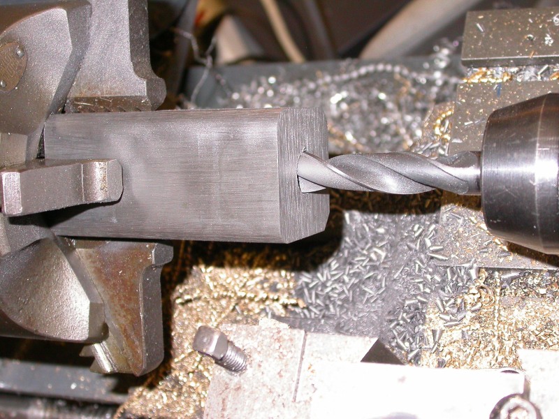
Photo 5
Having achieved the required sliding fit between the sliding block and the guide bar, the next exercise was to reduce the cross-section of the sliding block to the requisite 31mm X 35mm, keeping the axial hole still central to the finished bar. This isn’t terribly critical – it is far more important to keep the bored hole parallel to the axis of the bar than it is to have it accurately on axis. So, the 4-jaw independent chuck was pressed into service to face off each side of the bar in turn (Photo 6) to reduce it to the proper dimensions. Of course, equal amounts should be removed from each opposing pair of faces in order to keep the bored hole near enough central.
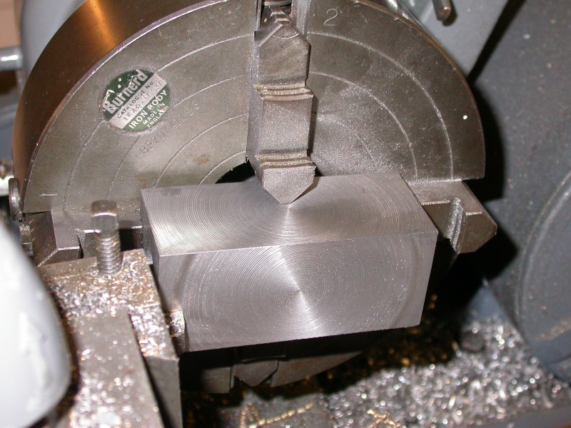
Photo 6
According to the instructions, the 5mm chamfers are then cut as per the drawings – again, this isn’t a critical piece of machining, so I pressed the belt sander into service for this job. The next thing the instructions tell you to do with the block is to clamp it in place on the underside of the table and spot through the four punched holes in the table before drilling/tapping them 4BA for the mounting screws that will hold the block in place. At this point, you realise that the two 4BA holes furthest from the operator will bisect the 45 degree chamfer that you have just put on that top leading edge, and that drilling these holes in the desired position will therefore be damn nigh impossible, and that you should have ignored the instructions and left the chamfers until after the drilling and tapping was all done. Consequently, after a hasty spot of re-machining, my sliding block now has a couple of 1BA Brass inserts that are drilled and tapped for the 4BA mounting screws. Such is life. So my recommended machining sequence is:
1. Bore the axial hole.
2. Reduce the cross-section to the proper dimensions.
3. Spot through the mounting holes in the work table onto the sliding block, drill & tap 4BA. Even better, clamp the block in place under the table and drill through the holes in the table directly into the block; I often find that spotting through followed by drilling results in a drilled hole that is slightly but annoyingly out of position.
4. Drill the mounting holes in the work table 4BA clearance, and countersink so the screw heads will be flush with the surface.
5. If you are planning to fit the traverse leadscrew (one of the add-on kits), drill and tap the 2BA holes on the underside of the block too.
6. Drill and tap the hole in the back of the block for the locking screw (25).
7. Machine the 45 degree chamfers.
It is also worth observing here that the 4BA screws provided are socket-headed countersunk screws that need a 1/16” hex wrench to drive them; I have a couple of sets of wrenches that have ones of that size, but they must have been manufactured from something marginally less durable than high tensile cottage cheese, so there was little chance of getting any torque on the screws. An easy solution to this problem is to use conventional slot-headed or cross-headed screws in place of the supplied ones, or convert the ones supplied to slot-heads with the aid of a hacksaw.
Machining the locks, screws, handles, and cams
There are a fair number of bits of turning to do to make various bits & bobs for the table traverse and angle setting mechanisms. Some of these parts will prove useful when machining the support and guide bars to length, so it is worth making these first (again, the received instructions aren’t very clear on this point, as in some places they call for the use of parts whose construction is described much later in the described sequence!)

Photo 7
Firstly, there is a pair of table stops with brass screws (14a &b) that allow the travel of the table to be limited in both directions. Photo 7 shows one of the table stop collars being bored out from a 3/8” length of 1” diameter stock. I often fit the boring bar upside down and use it on the back of the bore, so the swarf drops away from the tool rather than on top of it; the result is a much cleaner cut. The matching thumbscrews are machined out of brass; the end result can be seen in Photo 8.
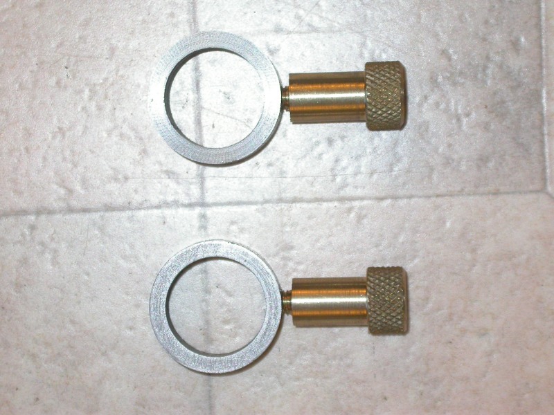
Photo 8
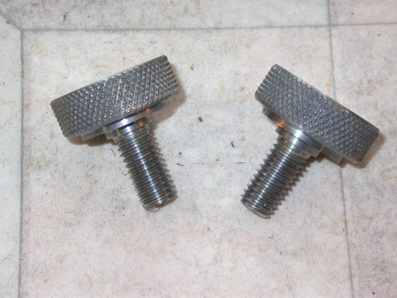
Photo 9
Next, a pair of knurled side plate clamping screws (16) for the sheet steel side plates (6) are machined up from 1” diameter stock – see Photo 9. These have a 10mm diameter shoulder at the end of the thread that is intended to slide in the slots at the base of the side plates; you will probably find that there is a bit more filing to do to allow this to happen – or at the very least, cleaning the paint out of the slots. Alternatively, you could of course machine the shoulder to fit the slot. The screws are threaded M6 to match the captive nuts inserted in the base assembly (1).
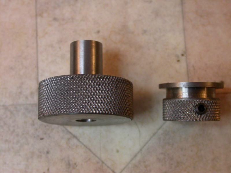
Photo 10
Next, the left-hand and right-hand knurled clamping nuts (13) for the cam bar table tilt assembly (Photo 10). The right hand one is machined from 1.25” diameter bar; it has a flange on the inner face that the drawings suggest should be graduated to represent the tilt angle – graduating it can only reasonably be done after everything else has been made and assembled, as there isn’t an easy linear relationship between the angle of tilt and the position of this knob. This knob has a smooth bore and is held in place on the end of the cam bar by a set-screw. The left hand knob is machined from 1.5” diameter stock, and is bored and threaded 3/8” 26 TPI; this is the knob that holds the cam bar in position once the angle of the table has been adjusted.
Next, the cam plates (11) and cam bosses (12) that support the rubbing strip at the front edge of the tilting table. There are three cams, fabricated from punched steel plates, each with a cam boss (a set-screw collar with a shoulder machined on one face) attached. The first job is to machine the plates to the correct OD, and then bore the offset holes to the diameter of the shoulder on the cam bosses. The instructions suggest that you drill a pair of holes through all three discs so that they can be attached to a square piece of timber that in turn can be held in the independent 4-jaw chuck; you then machine all three discs simultaneously so the OD and the bores are identical. They also “highly recommend” riveting or bolting the discs together so that they don’t move relative to each other during machining. Always ready to cut a corner if I can, I decided that the bolting/riveting wasn’t really necessary; suffice it to say that in hindsight I would elevate the “highly recommended” to “do this unless you want to continue to be a complete idiot, because a pair of woodscrews WILL NOT give you enough clamping force to keep the discs together”. Anyhow, I did eventually drill the extra holes for clamping bolts and managed to clean up the OD to a shade under, but close enough, the right diameter. Next, you use the 4-jaw to offset the timber “faceplate” to bore the offset hole, as seen in Photo 11. Now this gave me an excellent opportunity to put the hacker’s principle of “measure once, cut twice” into practice – for some reason that escapes me, after boring the offset hole, I discovered that it was rather nearer the edge of the disc than it should have been, so the chuck had to be re-adjusted and a second hole bored in the correct position near the opposite edge of the plates.
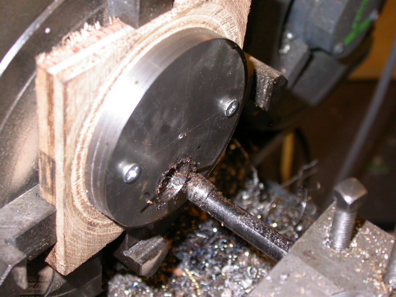
Photo 11
The cam bosses can then be machined – the smart thing to do here is of course to machine the shoulder to be a tight fit in the hole bored in the plate. The plates and bosses are then drilled and the bosses tapped 2BA for the screws that hold them together, and the bosses also drilled and tapped for the setscrews that will hold them in position on the cam bar. The finished articles are seen in Photo 12.
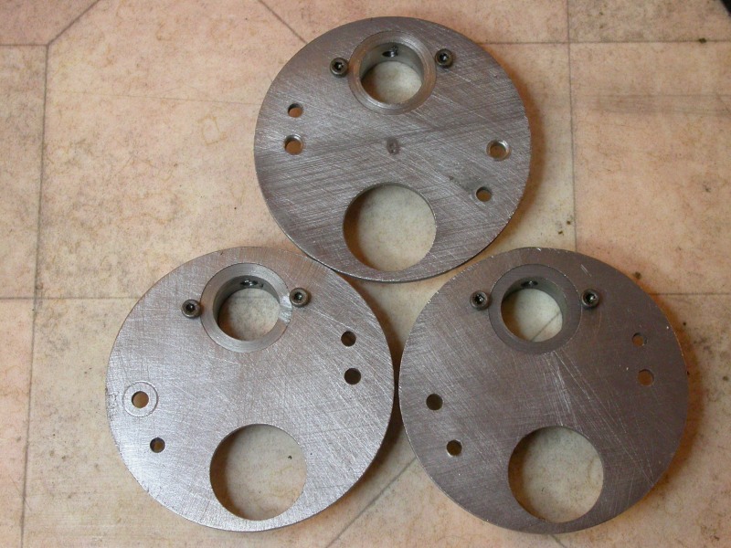
Photo 12
Finally in this section a set of 3 matching Brass thumb screws (25) – one is used as the locking screw for the work table’s sliding block; the other two are used later in the adjustable work-slide assembly. These are straightforward turning, knurling, and threading jobs; the only point to watch here is that the length of Brass bar supplied for these components is only just long enough, so you have to get a bit creative with machining the last one, or alternatively, as I did, fish out a longer piece of brass bar from the scrap box and use that to make the last one. The finished screws can be seen at the top of Photo 13.
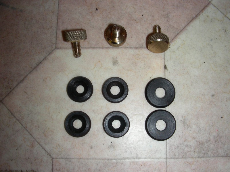
Photo 13
Machining the spacer bars and washers
The two side plates are held apart by the two spacer bars (8) and the guide bar (15); machining these to the correct length is therefore important if the table assembly is to be able to slide back and forward easily to adjust the distance between the work-slide and the grinding wheel. The instructions refer to a method described by Geoff Sheppard in his article in MEW Issue 71, which is basically to machine one end of each bar, then measure and mark the required length by fixing the side plates to the base assembly, with one plate offset so that the machined end of the bar can be inserted properly into its hole in the plate and the correct position of the other end marked against the offset plate. This is where you will find that machining the table stops and the cam bosses first comes in handy, as these can be fitted to the far ends of the bars and adjusted to the exact position of the second shoulder, and then used as a guide for scribing the shoulder position on the bar. Geoff advises inserting a sheet of photocopying paper (laser or inkjet would do fine) between the side plates and the base plate to ensure that the spacers are machined slightly over-length, thus allowing the table assembly to slide nicely.
There are matching washers to be machined for the spacer bars (9) and the guide bar (7); these are straightforward to machine, and the end results after blacking are seen in Photo 13. I found that the easiest way to machine them was as a stack, as seen in Photo 14; drill then countersink from the tailstock, use the cut-off tool to mark off the right thicknesses, then chamfer the outer edge and finish cutting off, then repeat.
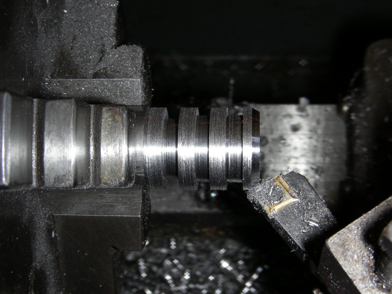
Photo 14
Once the spacer and guide bars are machined, the cam bar (10) is machined using a similar marking out procedure. This has a plain turned spigot at the right-hand end, as shown in Photo 15, to take the right-hand clamp nut (13); this is held in place with a set-screw, so it is appropriate to file a flat on the bar at an appropriate position. The other end is threaded to take the left-hand clamp nut (13), as seen in Photo 16.

Photo 15
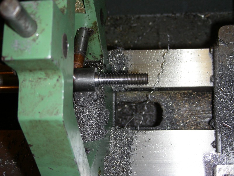
Photo 16
Well, that is, at least, the theory. In practice, because the base assembly is fabricated from folded sheet steel, you cannot rely on its sides being vertical, or even truly flat, and with my kit, when I attached the two side plates to the base they splayed out noticeably from bottom to top, the difference being about 3mm wider at the top than at the bottom. This meant I had two options; firstly to machine the bars to different lengths in order to maintain the splay, or secondly to machine them all to the same length, so that both side plates would be held parallel by the spacer bars, and then if need be adjust the length afterwards to give the assembly the required sliding fit. I didn’t much like the idea of the side plates not being parallel to each other, so I went for option 2. If you go this route, it is better to err on the long side for the bar lengths first of all, because there’s no easy way back if you machine the bars too short (don’t ask how I know this). Anyhow, after much trial and error, the assembly was made to fit, and the parts assembled; the result can be seen in Photo 17.
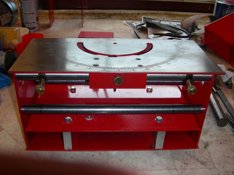
Photo 17
Building the work-slide assembly
The first step here is to assemble the base plate (17 in Figure 2) and the two guide bars (18). The base plate will eventually be brought to length on the lathe, by machining the bevelled arc that appears at the end furthest from the pivot pin, so any marking out needs to be done from the pivot pin end of the plate. Here again the instructions received with the kit are at a noticeable distance from reality in a number of important ways, so I will describe what I found to be a workable sequence of machining operations.
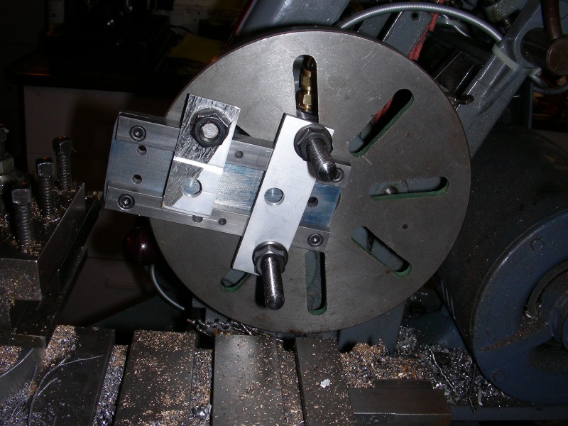
Photo 18
First, decide which end of the base plate will carry the pivot pin; mark this end to remind you that all measurements should be referenced to it. Clamp one of the guide bars in place, so that the pivot pin end of the guide bar and the base plate match. Mark out the guide bar for the three holes shown on the drawing for the 2BA cap screws that will hold the bar in place on the base plate; drill through both the guide bar and the base plate 2BA tapping size. Unclamp, and drill the 3 holes in the guide bar 2BA clearance and counterbore for the cap screw head. Tap the holes in the base plate 2BA and screw the guide bars in place. Using the 1” X 1” bar that will form the primary tool holder (27) as a spacer, clamp the second guide bar in place, and repeat the marking, drilling, and tapping process. At this point, you will probably find that the pivot end of the assembly could do with some truing up so that the ends are all flush; I did this using my belt sander, but filing would work too.
Next, mark out for the 6mm diameter pivot pin hole and the two 2BA clearance holes at the other end of the plate that will take the mounting screws for the feed nut. Drill and ream the pivot pin hole. Drill the other 2 holes; these need to be countersunk from what will be the underside of the base plate.
Next, mark out the positions for two 5mm diameter holes for the tool slide locking nut, these are drilled through both the guide bars and the base-plate, on a 60mm radius from the pivot hole.
Finally, disassemble and mark and drill 2 through holes, 2BA tapping size, through the guide bars, 1.25” from the pivot pin end of the assembly and tap them 2BA; these will be used for the clamp bar (21) and clamp column (20) mounting. Reassemble the guide bars to the base plate.
The base plate and the guide bars need to be radiused/bevelled at the same time, so the assembly is attached to a faceplate on the lathe, centred on the pivot hole, and the outer edge brought to a radius of 4.15”. Photo 18 shows this procedure part way through. Once the correct radius is reached, the outer edge is bevelled by 15 degrees by adjusting the topslide. The three fiducial lines, one central and the other two at -10 and +10 degrees, can conveniently be engraved at this point using a sharp lathe tool and your favourite in-lathe indexing method. The result so far can be seen in Photo 19.
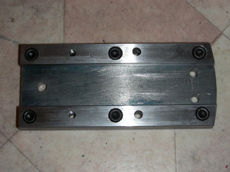
Photo 19
The tool holder and feedscrew bearing block
The primary tool holder (27) and the feed-screw bearing block (19) are machined from a single piece of 1” square FCMS bar. This is one place where I managed to come up with a machining sequence that was far worse than the one described in the instructions, so it is best to stick with them for this operation. The instructions recommend machining the bearing block before parting it off from the main bar; this allows the radius and chamfer at the top of the block to be machined by offsetting the bar by ¼” in the 4-jaw chuck. Take it from me, this is far easier than machining the radius and chamfer after parting off! Once the radius and chamfer have been machined, the bar can then be re-set so that its axis runs true, the axial hole drilled/reamed, and the block parted off from the bar. The bearing block can then be clamped in place on the work-slide, spotted through from the 2BA holes in the slide, and drilled 2BA for the two mounting screws. A further 2BA tapped hole in the top for the locking screw (25) completes this part. Photo 20 shows the bearing block fitted in place, with its locking screw.

Photo 20
The primary tool holder (27) is basically just a 1” square bar with an axial hole and two 2BA threaded holes on one face that take set-screws, one to lock the feed nut assembly in place at the back end, and the other to lock whatever secondary tool holder you choose to use. If you plan to use the primary toolholder as a means of indexing quarter turns (e.g., for touching up 4-flute end mills), then the set-screws should be shortened so that their heads do not protrude above the surface of the bar. Photo 21 shows the boring in progress. The design calls for this bore to be finished and reamed to 5/8”; this is where I took a slight deviation in the interests of improving the versatility of the tool holding system.
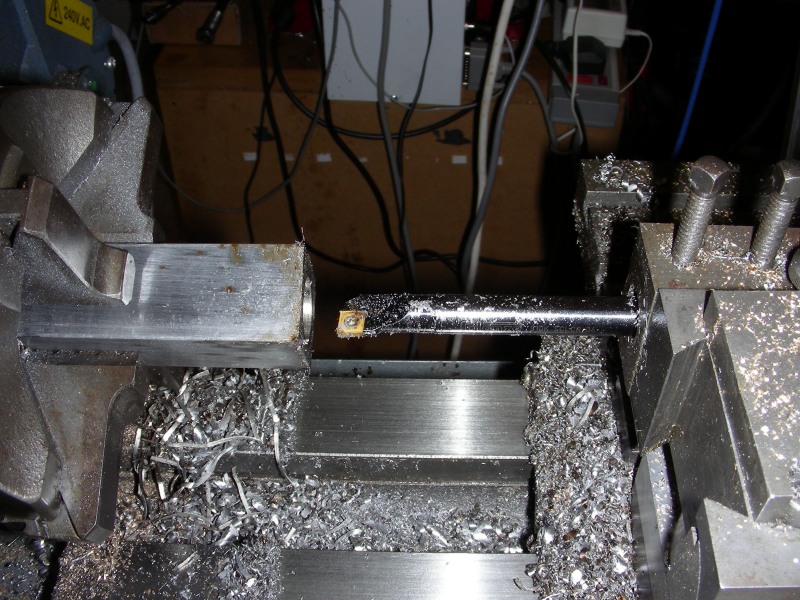
Photo 21
The basic design includes a lathe tool holder that carries the lathe tool at right-angles to the axis of the primary tool holder, and if you wish to grind end mills, these are carried in individually machined collets that fit the 5/8” bore. Giles Parkes wrote an article on 4-facet drill grinding, in MEW issue 64, where he describes a replacement tool holder for his Worden that caries ER20 collets; this got me thinking about alternative systems that didn’t involve machining individual collets for every size of shaft that you want to hold in the tool holder. Clearly, Giles’ solution is a good and workable one; you could hold the lathe tool holder in an ER collet and the end result would be the same as the original design. However, I happened to have a plain shank ER16 collet chuck to hand that I had bought a long time ago to use as a spindle for my Taig mill; as I had acquired an ER16 headstock for the mill, this was now surplus to requirements, and so seemed an easy way of achieving the versatility of a “proper” collet system without actually having to machine the collet chuck myself. The shank of the chuck is 16mm in diameter, ever so slightly larger than the 5/8” specified, so I bored and reamed the primary tool holder to fit the ER16 chuck’s shank. Plain shank chucks are readily available from tool suppliers; this one happens to use the compact “castellated nut” version of the collet closer. I found another variant on Ebay sold by a Chinese vendor for a very reasonable price that has a 20mm diameter shaft and a hex nut collet closer; both chucks are shown in Photo 22. The 20mm diameter shank version would fit within the 1” square tool holder, although there wouldn’t be much meat left for the set-screw. Other diameters of shaft are available too – I even found a 5/8” shaft variant that would work without changing the original design.
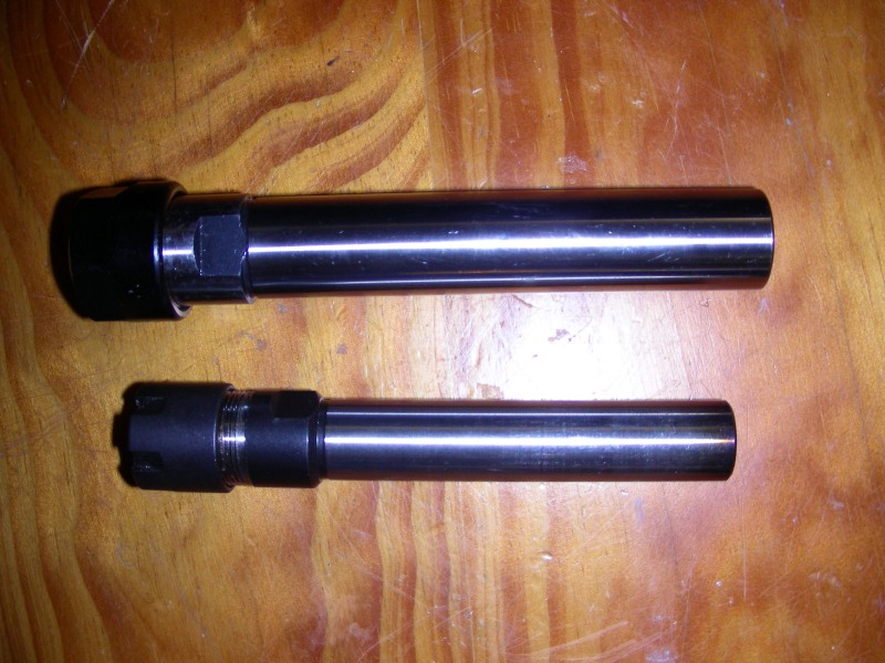
Photo 22
One problem with plain shank ER collet chucks is that, although they generally have a through hole, it is usually significantly smaller in diameter than the maximum capacity of the collets. ER16 collets can accept up to 10mm diameter, and for this particular purpose, it is ideal if the through hole matches (or slightly exceeds) the maximum collet capacity. Obviously, the chuck is hardened steel, so conventional drilling was out of the question; this was another opportunity to press a masonry drill into service. Once the drill was licked up to give a nice sharp pair of cutting edges, it made short, if rather noisy, work of boring out the shank of the collet chuck to a shade over 10mm, as seen in Photo 23.
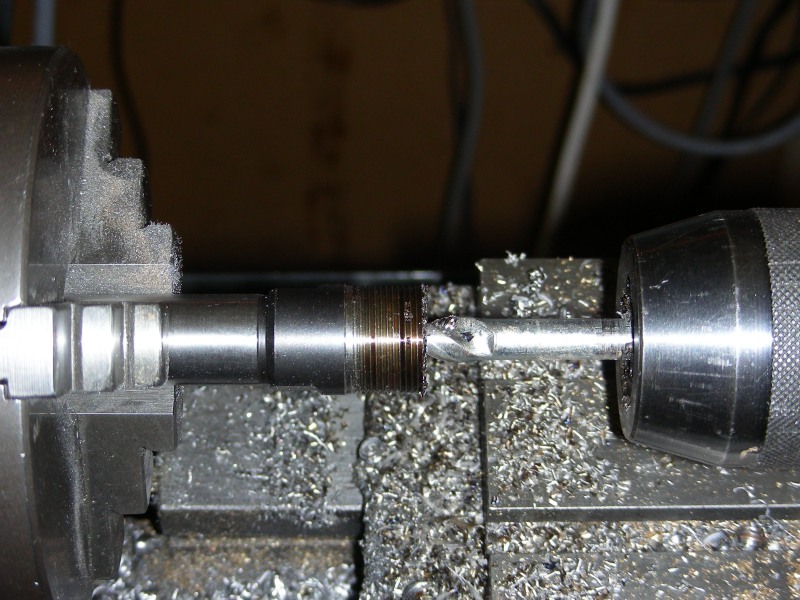
Photo 23
The primary tool holder is locked in position by the clamp bar (21) which sits on top of two clamp columns (20) and carries one of the locking screws (25); making these parts is a simple machining and filing exercise. These parts can be seen in position in Photo 24.
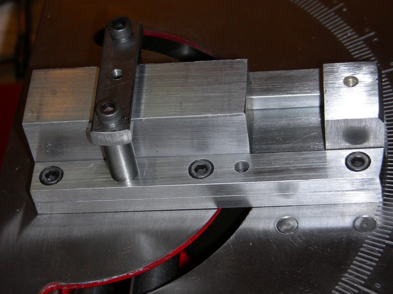
Photo 24
The lathe tool holder is another simple piece of machining; it consists of a spindle (29b) that fits the bore of the primary tool holder, which fits into the tool carrier (29a), which is machined from 1” X 1.25” steel bar. Making these parts is very straightforward; the length of the tool holder isn’t critical, and the only oddity is that the end of the spindle that fits the tool carrier is machined with a 10 thou eccentric so that the final assembly can be adjusted to ensure that the tool carrier sits firmly on the table when the spindle is fitted to the bore of the primary tool holder. The two components are Locktited or Super-glued together when the eccentric has been properly adjusted. The instructions suggest that a 1/8” hole can then be drilled through both parts, and a 1/8” pin fitted for extra security. Alternatively, as I did, you can forget to “peck” drill, and let the drill get so clogged with chips that it snaps off in the hole. Ah well, the snapped off drill probably serves the same purpose as the 1/8” pin!
The whole work-slide assembly is locked in position by a locking screw (26a) and a locking nut assembly (26b). The screw is a simple turning, knurling and threading operation. The locking nut assembly is basically a circular “T” nut, with a pin that prevents it from rotating in the semicircular slot in the table. The only points worthy of note here are that the smaller diameter of the nut has to be able to slide freely in the slot; either the slot needs to be filed, or the nut reduced in diameter, to suit. Also, the larger diameter of the nut has to be able to slide past the sliding block that supports the table; this is where you discover why there is a chamfer on the block (the one that caused the trouble earlier on). To allow the nut to slide past unimpeded, you may need to chamfer its underside to match the chamfer on the sliding block. Alternatively, you could increase the chamfer on the block. Whether this is necessary or not will be obvious once the locking assembly is in position and you try to slide the work-slide assembly past the zero degree mark on the table.
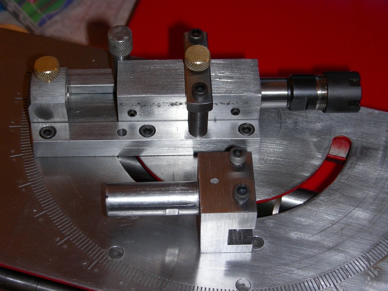
Photo 25
Photo 25 shows the work-slide and tool-holder components constructed so far, with the ER16 collet chuck fitted to the primary tool-holder, and the lathe tool holder assembly in the foreground. On the latter, you can see the small flat machined in the spindle to take the locating set-screw; note that I have chosen to mount the primary tool holder with the set-screws horizontal rather than vertical, as this way they don’t interfere with the locking screw.
The feedscrew and feed nut assemblies
The feedscrew (31), graduated thimble (32), and thrust collar (23) were the next components to be tackled. I happened to have a spare commercially made set-screw collar of the right size, so I pressed this into service rather than machine one myself.
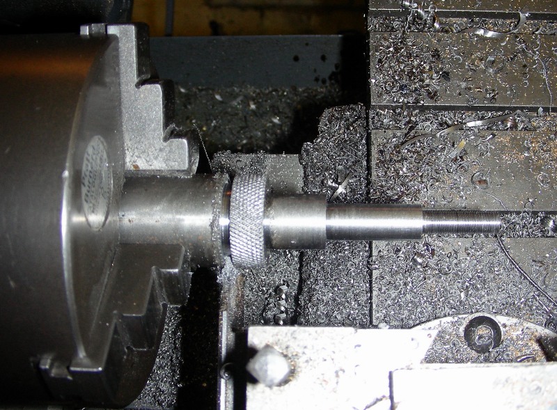
Photo 26
The feedscrew is machined at a single setting, and is pretty straightforward (Photo 26); the instructions suggest that cutting the screw thread on the lathe is preferable unless you have a sharp 40TPI die, but as I had a brand new unused tap and die, supplied by Hemmingway, I decided to make use of these. The first pass on the thread was done with the split die opened out as far as it would go, with the part still in the chick and using a hand die holder, but with pressure on the back of the die holder from the tailstock chuck to keep the die square to the axis of the lathe. This technique works very well, and allows threading with a die to be done under power if like me you have a variable speed control with a “jog” facility on the lathe.
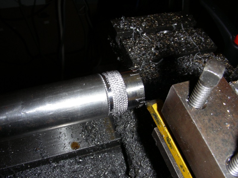
Photo 27
The graduated thimble is a slip fit over the feedscrew. As this part has a matching knurl to the feedscrew, it is advisable to do the knurling before boring it out, in order to avoid the knurling distorting the part. Photo 27 shows the thimble being graduated; a full turn is 25 thou, so 25 graduations is appropriate, with every fifth graduation rather longer than the rest. Number punching could also be added if desired. Graduation is best done in the lathe before parting off from the bar; as I have a headstock dividing attachment for my lathe (visible on the left of Photo 28), I used that, but there are plenty of other approaches that can be taken to achieve the same result. A sharp threading tool turned through 90 degrees makes a great scriber, as can be seen in the photo. As a slight digression, my dividing attachment is stepper motor driven, and I use one of my DivisionMaster controllers to drive it. The lathe is CNC converted, and for simple operations like this I often use a DivisionMaster controller to drive the leadscrew, which makes it easy to get the length of traverse right for machining accurately to a shoulder. So on this occasion, I had two DivisionMaster controllers running, one rotating the spindle to the correct position, and the other operating the saddle traverse to make the marks on the thimble a consistent length; the result is probably about as painless as it gets when it comes to engraving parts like this.
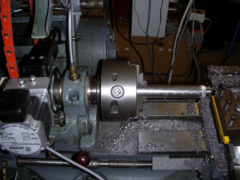
Photo 28
Once the graduation has been done, the thimble is bored out to a slip fit on the feedscrew, and opened out at the graduated end to allow a short length of 1/8” spring steel to be inserted between the screw and the thimble to allow the thimble position to be adjusted relative to the feedscrew. The finished thimble can then be parted off and fitted to the feedscrew. One point that needs checking here is that the thimble should be slightly shorter than the nominal 5/8” length of the 0.594” diameter section of the feedscrew, because if it is longer than that, the thimble ends up acting as the thrust bearing on that side of the bearing block. Similarly, if you machine the recess for the spring steel friction strip to exactly 1/8” long, chances are that the steel strip will protrude slightly beyond the end of the thimble, so it is worth machining it slightly longer than the 1/8” shown on the drawing. Photo 29 shows the feedscrew assembly in position.
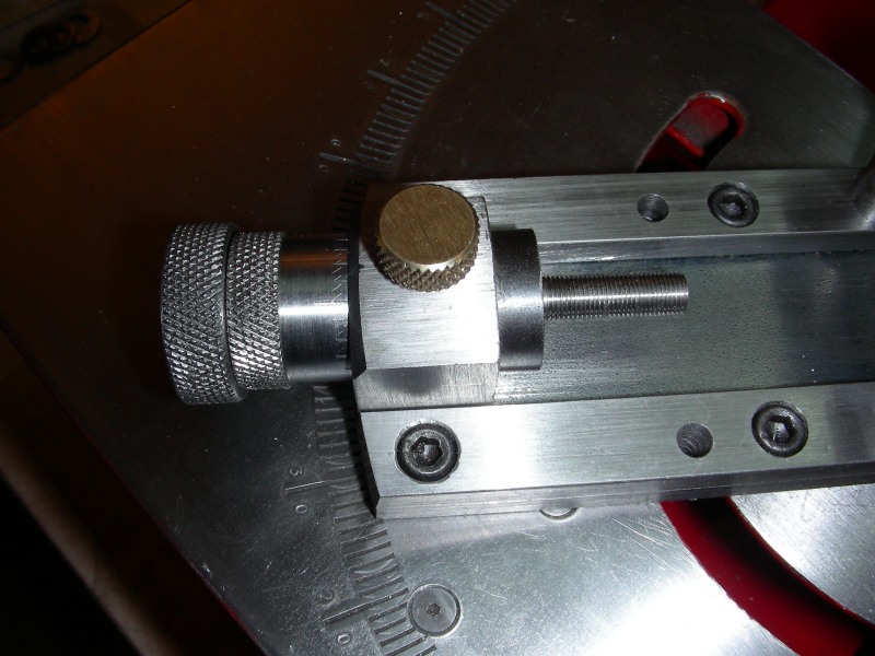
Photo 29
The feed nut (22) is held in a part simply labelled as “Adapter” on the drawings (28) by a set-screw, and the adapter is in turn held in the bore of the primary tool holder by a set screw. I have to say I didn’t fully understand this particular bit of construction – it seems to me that it would be rather simpler to make the adapter and feed nut as a single part, but there may be a good reason for this that relates to the other accessories that can be added to the system, so I went along with the design as stated. Threading the feed nut was done using a tap held in the tailstock chuck before the part was parted off from the bar; the tap supplied by Hemmingway was a taper tap, and the non-tapered part of its length was just a shade over ½” long, so threading the entire length of the feed nut was problematic. I ended up attacking the tap with my bench grinder to reduce the diameter of the shaft behind the threads so that it was less than the core diameter of the threads, so the tap could feed all the way through the feed nut (see Photo 30) – of course, this would have been a tidier bit of grinding if my Worden had been completed. There’s not a lot more to say about these parts, other than that I chose to vary the dimensions a little – my “adapter” is only ¾” long, because I chose to place the set screw that locates it in the primary toolholder at only ¼” from the end, and I made the flange only ¼” thick instead of ½”; these mods are intended to (a) allow the ER collet chuck to fit a little further into the primary tool holder and (b) allow the feedscrew to draw the primary toolholder further away from the wheel to accommodate longer items in the chuck. Photo 31 shows the completed slide and feed screw assemblies.
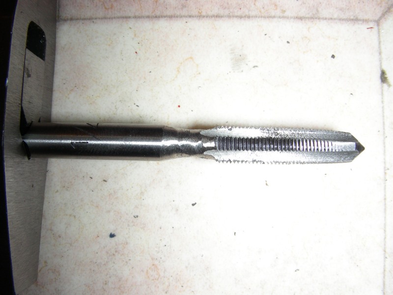
Photo 30
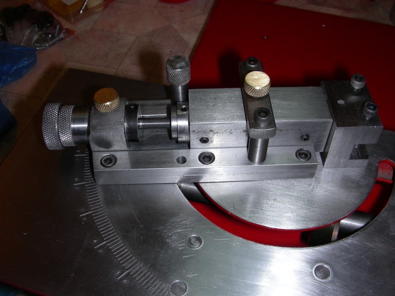
Photo 31
The electrical bits
The next stage is to wire up the motor and the forward/off/reverse switch, and assemble the motor on its plinth in position on the main base plate.
As with all mains electrical work, if you are in any doubt as to your competence (and the relevant word here is competence, not confidence!), then do the safe thing and get a competent electrician to wire it up for you.
Here, the instructions provided with the kit are good and clear; however, they do mention that the source of motors may vary from kit to kit, and therefore that the detailed labelling of the wires in the motor’s terminal box may vary from what is described in the text and the diagrams. This was certainly the case with the motor that I was supplied; the text talks about 2 windings and a capacitor, but the motor I have is also fitted with a thermal cut-out switch for which there is no sensible provision in the wiring scheme as described, so I left it disconnected. I figured that a thermal cutout is a smart idea for an application where the motor is likely to be run continuously and unattended, but since that is not the case with a grinder, where the use is both attended and intermittent, its utility is marginal to say the least.
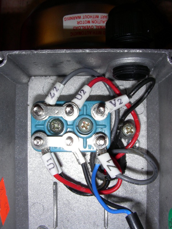
Photo 32
Photo 32 shows the terminal block that can be found by removing the motor’s terminal box cover plate. There are four sets of wires; a black and a blue wire that connect to the capacitor (which is out of shot at the bottom of the photo), a pair of grey wires that are the ends of the Starter winding, labelled Z1 and Z2, a pair of red wires that are the ends of the Main winding, labelled U1 and U2, and a pair of black wires that are for the thermal cut-out switch, labelled V1 and V2. If you are in doubt as to which winding is which, or if the colours differ from the ones in the photo, connecting a multimeter on its low range resistance setting across them will reveal a small difference (a couple of Ohms) in the winding resistance, the Starter winding being slightly higher in resistance than the Main winding; also, in the wiring of the motor as supplied, the capacitor is wired in series with the Starter winding. The connections to the cut-out switch will show a short circuit on the meter. If you don’t own a suitable multimeter, then now is probably the time to admit that you are not competent to complete this task and get an electrician to do the work for you.
Having figured out which wire is which, the next thing to do is to disconnect the cut-out switch wires (if your motor has them), tuck them out of harm’s way, and re-arrange the four motor winding connections on the terminal block so that each goes to its own terminal post, as shown in the wiring diagram supplied. The instructions suggest that the capacitor should be removed and mounted along with the switchgear in the motor plinth assembly (2); there is no good reason to do this, and I found it easier to assemble the motor, plinth, mains lead, 3-way terminal block, and switchgear without having to think about the capacitor at the same time. If you connect the capacitor in series with the Starter winding in the motor’s terminal box (the capacitor wires are different colours but it doesn’t matter which way around it is connected), and replace the capacitor as shown in the wiring diagram with a simple wire link, then the end result is electrically identical.

Photo 33
The connection between the wiring in the plinth and the motor box is made using a supplied length of 5-core cable. The instructions talk about this wire having 2 black cores (which it refers to as Black 1 and Black 2); mine had one black and one grey, which made life a little simpler. The green/yellow wire is screwed to the earth terminal in the box; the other four wires are connected to the motor windings, as per the instructions. The end result can be seen in Photo 33; note the capacitor is located in its original position in the motor box, protected by plastic foam. I chose to use ring crimp terminals on the wire connections like the ones used on my motor – these are crimped onto the bare wires and are terminated in a washer that fits over the screw posts on the terminal block, and they make a far better and safer job of this kind of wiring than attempting to stuff a twisted (or twisted and soldered) wire under a washer. The 5-core cable passes out through the gland on the terminal box; don’t forget to tighten the outer screw cap of the gland to grip the cable firmly and prevent strain on the connections inside. The other end of the 5-core cable passes into the motor plinth through one of the glands supplied in the kit. There isn’t a lot of play in the cable, so you will probably find that it is easier to wire up the rest of the gubbins before attaching the motor to its plinth, or alternatively, attach the motor to the plinth first, then wire up the switchgear and the mains connections inside the plinth, then wire up the motor terminal box last. Either way, the connections inside the plinth are as described in the instructions, with the one change already mentioned if you choose to leave the capacitor in the motor terminal box. Remember to connect the mains earth to the sheet metalwork; one of the motor mounting bolts inside the plinth is the obvious place to do this. The inside of the wired-up motor plinth can be seen in Photo 34.
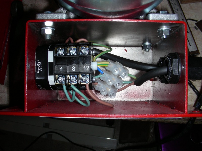
Photo 34
Once you are happy with the connections, it is worth going over them one more time just to make sure, before assembling the motor to the motor plinth (this is non-trivial because of the need to fit washers and nuts at the far end of the box), the switch to the motor plinth (make sure it is the right way up) using the right plastic plinth supplied – the one that will take the legend plate – and stick the legend plate in position using the double sided sticky pads supplied. The switch knob can then be fitted, the back fitted to the plinth, and the whole motor and plinth assembly fitted to the main base assembly. If you have painted the sheet metalwork, as I did, please check that there is good electrical continuity between the mains earth and all of the other bits of metalwork, including the motor frame; if necessary, a spot of judicious scraping will fix this. Also remember to fit the mains plug with a 5A fuse. If all is well, the motor should whirr nicely in forward and reverse directions as indicated on the switch legend. The machine as assembled so far can be seen in Photo 35.
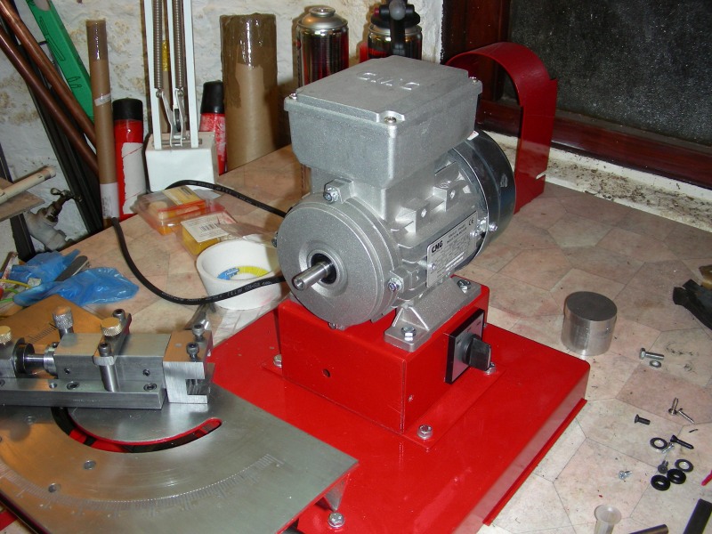
Photo 35
The cup wheel mounting hub
Figure 3 shows the components of the hub. The motor as supplied has an 11 mm diameter shaft cut with a 4mm keyway; just before the shaft disappears into the motor bearing, there is a slight shoulder, which conveniently acts as a stop for the hub to locate against. The hub is designed to fit the supplied 1.25” bore cup wheel; as I also have a diamond cup wheel with a smaller 20mm bore, I will in due course be making a second hub to accommodate this. It is probably worth making individual hubs to suit each different wheel that you plan to use, so they can be fitted and re-fitted without having to true up the wheels each time.
There isn’t anything particularly difficult about the construction, other than the need to bore the wheel hub (33) to a good fit on the 11m motor shaft. The instructions suggest that, in the absence of a handy 11 mm reamer, you machine up a plug gauge to ½ a thou smaller than the shaft, and bore the hub to fit the plug gauge; having gone this route, I would strongly recommend investing in an 11 mm reamer, particularly if you plan to make more than one hub assembly.
The wheel hub has a clamping washer (35) that holds the taper cup wheel (34) in position via three cap screws equally spaced around a circle; this was another opportunity to press the headstock dividing attachment and DivisionMaster into service to do the indexing. To drill and counterbore the bolt holes, the instructions show a picture of one of the Hemmingway “Quickstep” Mills in use. Not having one of those to hand, I rummaged around in my tool cupboard and unearthed a venerable but very noisy Black and Decker mains powered hand drill for which I had a bench clamping bracket. A few minutes of hacksawing and drilling reduced the size of the clamping bracket to manageable proportions and attached a piece of aluminium angle that allowed the whole contraption to be clamped in the toolpost of the lathe. Photo 36 shows the washer and hub being spot-drilled in three places before being drilled 2BA tapping, then the clamping washer is drilled 2BA clearance, and finally the washer is counterbored to suit the cap head screws. A further use of the Black & Decker toolpost drill contraption can be seen in Photo 37, where it is being used to cross-drill the hub, on one side for the 4 mm Key (36) and on the other side for the 2BA locking screw and pressure piece (37). Adjusting the drill height so that it cross-drills accurately on the diameter is pretty straightforward; if you trap a 6” steel rule between the end of the drill and the workpiece, and adjust the drill height until the rule is vertical, then you are pretty much on axis (the same technique works well for setting lathe tool height too). A point worth noting is that these two holes should be drilled 4mm, which is slightly larger than necessary for tapping 2BA (I usually use 3.9mm), in order for the key and pressure piece to fit correctly as designed. The brass pressure piece is put under pressure by a 2BA set screw. The key is made in one piece from silver steel, slotted at the end with a hacksaw to make a screwdriver slot, then hardened and tempered.
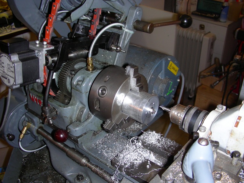
Photo 36
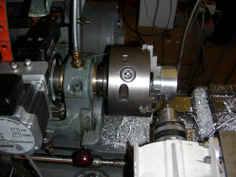
Photo 37
Final tweaks
The construction is now complete, unless you plan to make the collet system described in the instructions for holding end mills. I don’t plan to do this, as my need for holding round objects is now met rather more easily by the use of the ER16 collet chuck.
Having fitted the wheel and wheel guard to the grinder (see Photo 38) I realised that it would be a good plan to reduce the length of the collet chuck to the point where there is as little overhang as possible, so I hacked about 20mm of the end of its shank. This is of course not that easy, as the chuck is hardened, but possible with the aid of a Dremel-style hand drill fitted with an abrasive cutoff disc. A better solution is of course to follow Giles Parkes’ lead, and make a primary toolholder with an integral chuck.
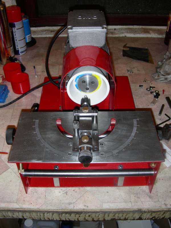
Photo 38
The final operation before the machine is usable is to true up the cup wheel with a diamond dresser. I had bought one of these a while back, and after adjusting its shank diameter to fit my largest ER16 collet, a quick pass across the face of the wheel cleaned it up nicely.
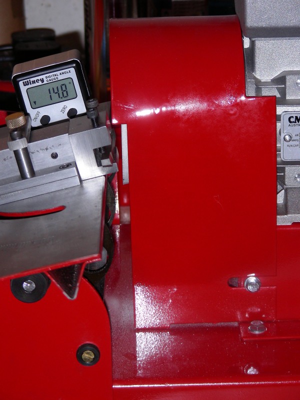
Photo 39
At this point I decided to try setting the machine up to grind a ¼” square lathe tool for my Peatol lathe. Tipping the table up by 15 degrees to give some side clearance immediately revealed a problem – the wheel guard wasn’t able to move far enough back to allow the top half of the grinding wheel to be used. The problem can be seen in Photo 39; with the guard pushed back as far as it can go, the lip at the top protrudes forward of the plane of the grinding wheel. In passing, note the use of a digital angle gauge to adjust the angle of the table; as I had one of these to hand, I figured that this was a better and more accurate solution than attempting to graduate the cam bar adjustment knob (13). You can see in this photo that the top edge of the guard is hard up against the motor terminal box, and yet the adjustment slot still has about half an inch of potential movement to the back. My guess is that this is a consequence of newer motor designs being used that have larger terminal boxes, and the design of the guard not being updated to match. So, there was nothing for it but to hack at the guard with suitable instruments of destruction. After cutting away a strip about 14mm wide and 80 mm long from the top of the guard, using hacksaw and abrasive wheel, it can now slide back as far as the adjusting slots will go, allowing the whole of the front face of the wheel to be exposed if so desired. The result can be seen in Photo 40, and Photo 41 shows grinding of the lathe tool in progress.
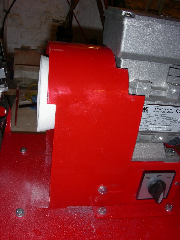
Photo 40
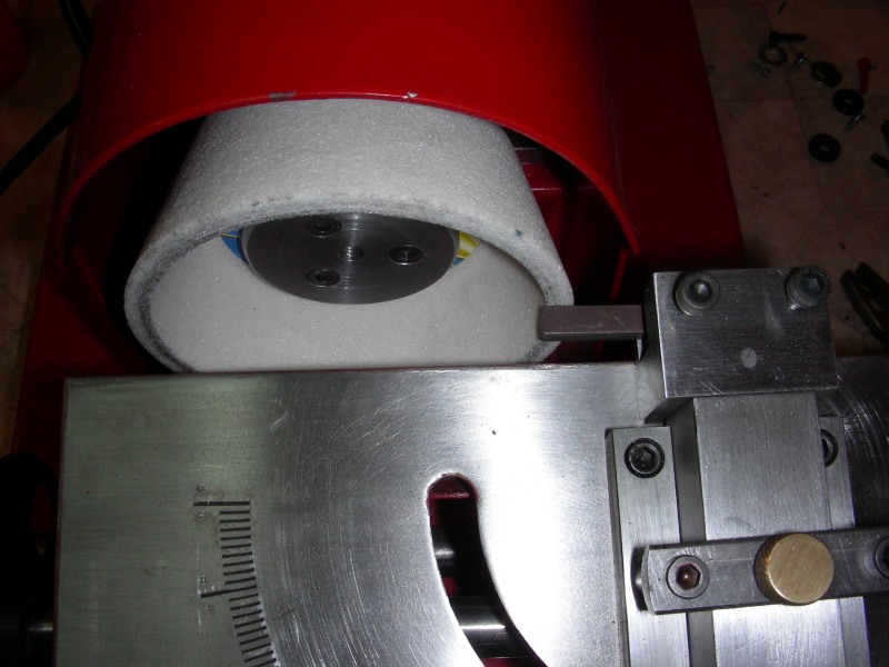
Photo 41
Another point to make regarding the wheel guard is that its dimensions limit the size of grinding wheel that can be accommodated in the machine as designed; firstly and most obviously, in terms of diameter, but secondly, in terms of depth. The dimensions of the wheel hub have been chosen so that the standard cup wheel is accommodated in the wheel guard; however, the diamond wheel that I plan to use in the machine has a much shallower dish, and therefore I will need to use a longer hub to place the working face of the wheel far enough forward (towards the operator) to clear the guard. This is of course another excellent reason why making individual hubs to match each of your wheels is a smart idea.
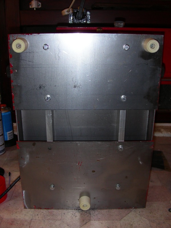
Photo 42
The only other addition to my machine so far is that I have fitted the base with 3 rubber feet, two at the front and one at the back, as seen in Photo 42; without feet of some kind, the base sits on the heads of the screws used to locate the aluminium stiffening bars (5), which isn’t terribly satisfactory. Rubber feet also provide some degree of vibration isolation, which is desirable. The feet were attached by drilling/tapping 2BA and screwing them in place with a dab of Superglue on the threads acting as a threadlocker.
Conclusions
All in all, this was a very enjoyable exercise, and apart from the various minor problems with interpreting the drawings and written instructions that I have mentioned in the text, all went pretty smoothly. I haven’t had a chance to use my Worden very much so far, but from the quick and dirty test on the ¼” square Peatol lathe toolbit, it looks as if the machine will satisfy my lathe tool grinding needs very well indeed, and I am sure that it will get used for many other grinding operations as well in years to come.
I had a quick play to see whether my ER16 chuck adaptation would allow me to do 4-facet drill grinding using the method described by Giles Parkes in MEW Issue 64, and it looks possible, albeit with a little modification. The table on my machine won’t tilt sufficiently far to get the desired 121 degrees between table and wheel face, but obviously one can achieve this by rotating the tool slide instead. Tilting the table up to get the 25 degree clearance for the first pair of facets is within the machine’s adjustment range; however, because the far edge of the table is lifted in order to achieve this, you then end up working pretty much at the top edge of the grinding wheel, so a raising block that would lift the motor plinth an inch or so would be desirable in order to make this a more straightforward exercise. I seem to recall an article in MEW describing an adaptation of the Worden to suspend the motor assembly from a vertical column in order to make it height adjustable; I may have a think about what is needed/desirable in that line at some point. Of course, I still have my free 4-facet grinding kit sitting on the bench waiting to be built, so maybe it would be best to build that first and see whether it makes the process more workable. I will, of course, describe my experiences with the 4-facet kit in a future article.
My thanks to Kirk Burwell at Hemmingway Kits for permission to reproduce extracts from their drawings as part of this article, and for their always friendly, courteous and speedy service.
Suppliers and other contact details:
- Hemmingway Kits, 126 Dunval Road, Bridgnorth, Shropshire, WV16 4LZ, UK. Tel: 01746 767739 Website: http://www.hemingwaykits.com/
- DivisionMaster controllers are no longer in production.