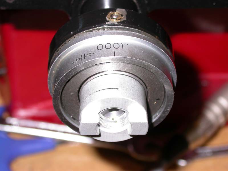
Photo 1: Oldham coupling half in position on X-axis leadscrew
Copyright © Tony Jeffree, 12th March 2006. All rights reserved.
Dick Stephen has written extensively in Model Engineers' Workshop magazine of his experiences with CNC conversions, and most recently on converting an X3 mill to CNC. Dick kept me updated with his progress as he performed his conversion, knowing that I planned to do a similar conversion in due course, so I not only had the benefit of seeing his articles before attempting my own conversion, but also the benefit of having talked through some of the techniques with him at various times.
The overall approach I took was broadly the same as Dick has described - replacing the leadscrews on all axes with 2mm pitch THK ballscrews, using size 23 stepper motors, and so on; however, my conversion differs in a number of details from Dick's. As some of these detailed differences may be of interest to other would-be CNC-ers, I decided to put together a small article to describe them.
Installing the leadscrews in the X and Y axes proceeded pretty much as Dick described in his articles (MEW December 2004/January 2005). However, I used a couple of short cuts:
- Dick modified the existing bronze Acme feed nut for the Y axis to act as a mount for the ballnut, but replaced the X axis feednut with a new, slightly larger piece of bronze machined to fit in its place. I decided that the X axis nut was just big enough to be machined out to hold a ballnut, which saved a little time and effort.
- It is necessary to provide end float adjustment for the thrust bearings on these axes. I realised that by threading the leadscrew half of the Oldham coupling M12 it could perform two jobs - adjusting the end float and coupling to the motor. This has the advantage of keeping the leadscrew extension as short as possible, so the motors stick out a little less. Photo 1 shows one of the threaded coupling halves in place on the X axis. I used the clamp type Oldham couplings, and used a little Locktite threadlocker on the threads before adjusting them to their final position.
Photo 1: Oldham coupling half in position on X-axis leadscrew
With the Z axis, I also adopted a slightly different approach to Dick''s; he used a 2:1 toothed belt/pulley reduction drive, mounting the motor at the bottom of the leadscrew. A significant part of his decision was to make sure that the Z axis motor wasn't underpowered for the job; the 2:1 reduction drive meant that there would be plenty of torque available for this job, which has to contend with the mass of the head and the frictional resistance imposed by the gas strut that is fitted as a counterbalance for the head. I decided that there should be ample torque and mechanical advantage around to dispense with the reduction drive, and opted for direct drive to the leadscrew as with the X and Y axes.
The logical conclusion of this decision was to place the motor on top of the Z axis casting rather than at the bottom of the column. So, as shown in Photo 2, it was a simple job to fit one of the motor mounts that DivisionMaster used to sell for converting rotary tables for CNC use to the top of the column, and drill a hole through the top of the casting to allow the leadscrew to be extended up into the mount. Photo 3 shows the top of the leadscrew in place; I simply extended the ballscrew by drilling and reaming the end 8mm diameter to a depth of 40mm and Supergluing a length of 8mm silver steel into the orifice. Of course, concentricity is the name of the game here, so careful machining and setup for the gluing operation are important, but it is perfectly achievable with care.
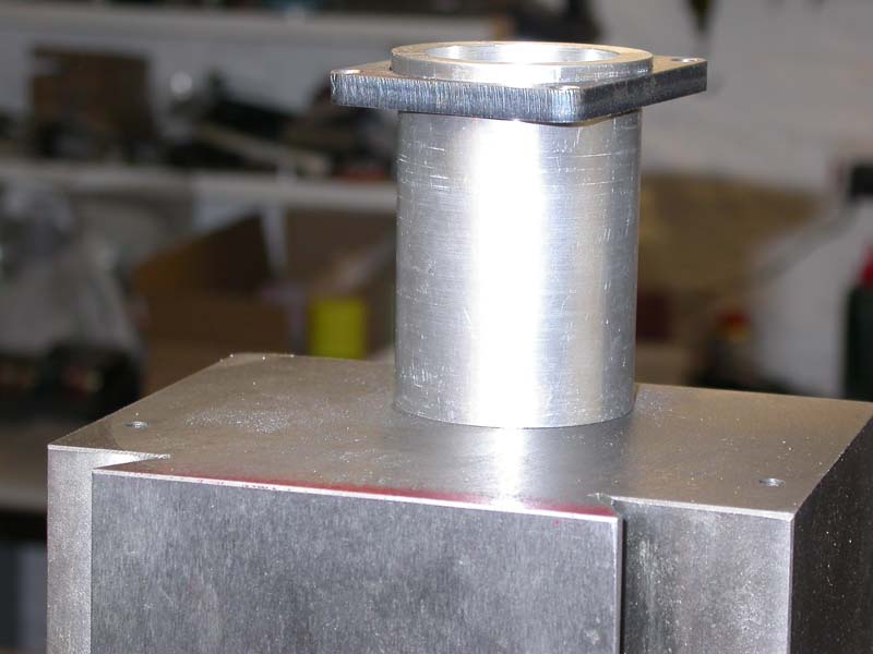
Photo 2: Motor mount in position atop the Z-axis column
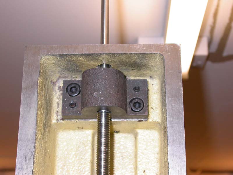
Photo 3: Z axis extension detail
Having decided to go this route, and not needing to modify the bottom end of the leadscrew to take a pulley, I decided that the easiest approach was to re-use the bottom end of the Acme leadscrew and thereby remove the need to machine a completely new extension piece to add to the bottom end of the ballscrew. Photo 4 shows the result; the bottom end of the leadscrew was again drilled/reamed 8mm to 40mm depth, and the bottom end of the Acme leadscrew was chopped off, allowing enough length so that I could machine down the Acme thread to give an 8mm diameter spigot that could be Superglued into the ballscrew, again with care taken to ensure concentricity.
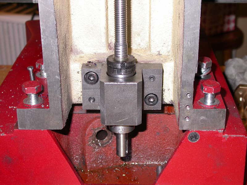
Photo 4: Bottom support of Z-axis leadscrew
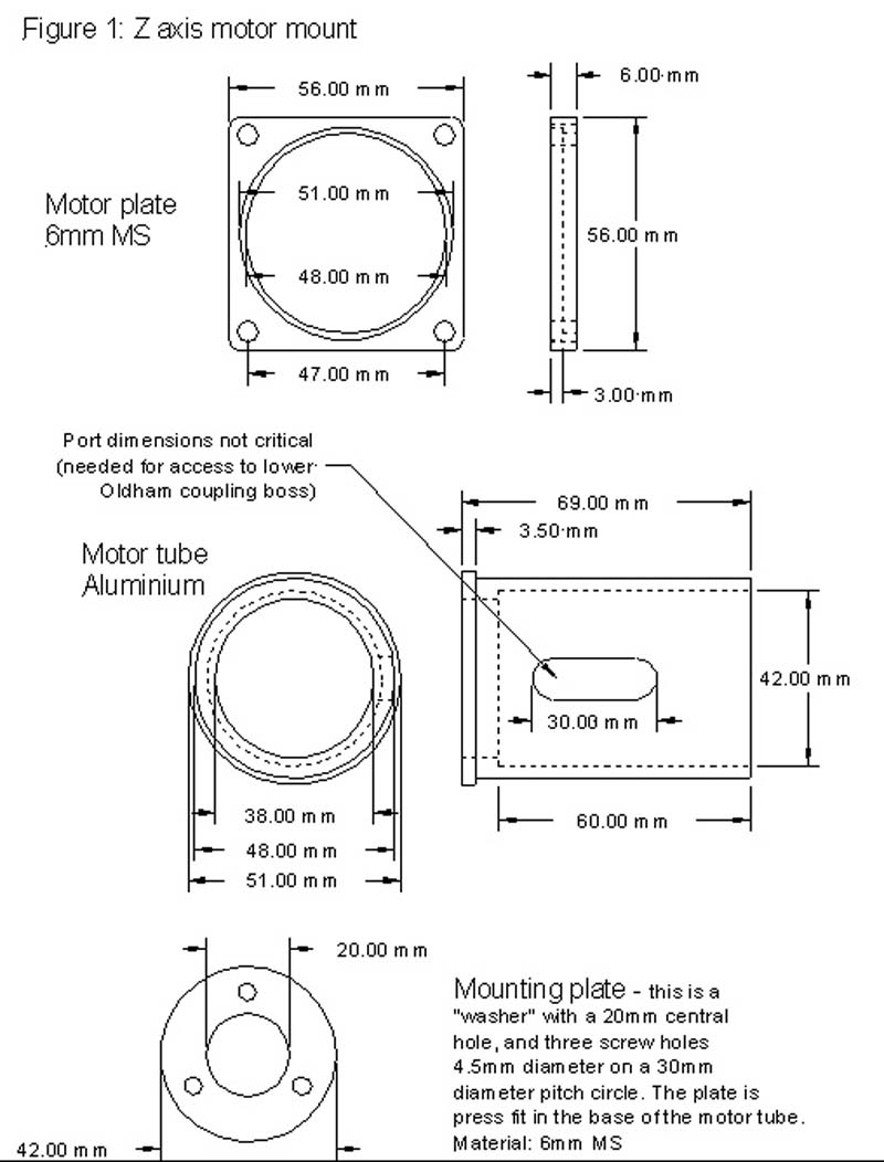
I have already mentioned the Z axis mount; this is essentially an aluminium tube with a flange at one end that a square motor mounting plate locates and locks against, and a circular plate inserted into the other end (see Photo 5 and Figure 1). The circular plate has a central hole for the leadscrew shaft, and three mounting holes for M5 screws. Normally, this mount is used by DivisionMaster to convert Vertex and similar rotary tables to CNC; the mounting holes are the same size/spacing as appear on the division plates for these tables.
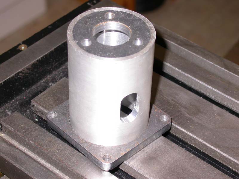
Photo 5: Motor mount - un-modified
The same motor mounts were modified to use on the X and Y axes, essentially by shortening them and reducing the internal diameter at the open end and fitting a pair of setscrews to clamp them in place. The dimensions of the modified mounts can be seen in Figure 2. They are designed to fit in place of the chromed ring that is pressed over the thrust bearing housings on the X and Y axes - this ring can be seen in Photo 1 and can readily be removed by inserting a thin piece of metal behind it with the help of a hammer (a light tap on the back edge of a Stanley knife blade worked for me!) to get it started before resorting to more robust levers. The boss underneath is 40mm in diameter. The mounts are held in place with a couple of setscrews 90 degrees apart. Photo 6 shows the X axis mount in place, and Photos 7, 8, and 9 show motors in place on the Y, X and Z axis mounts respectively. Note that the Y axis motor shown is smaller than the other two - this will be explained in the next section.
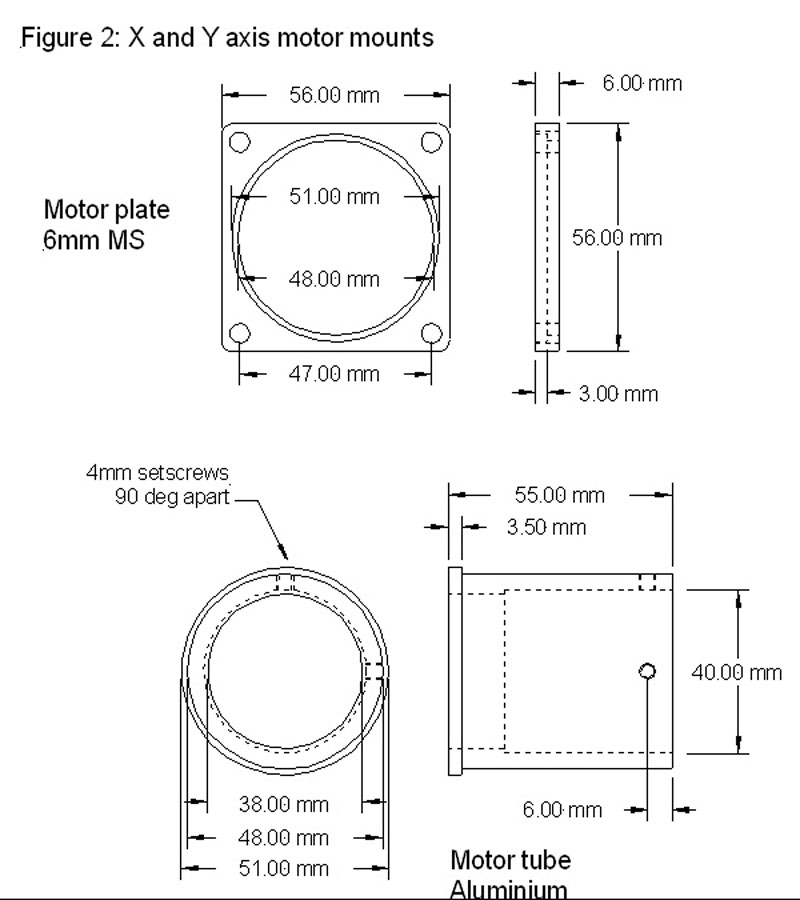
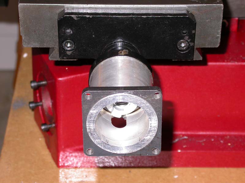
Photo 6: Y-axis motor mount fitted
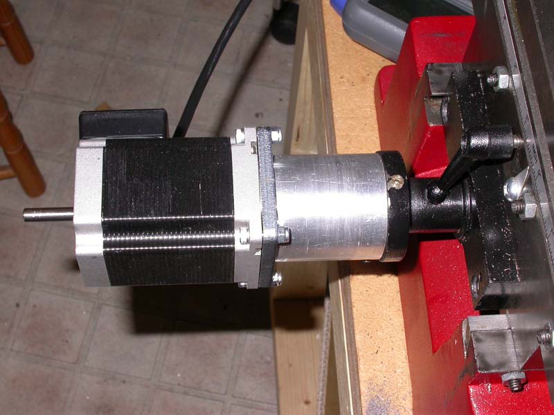
Photo 7: Y-axis motor fitted
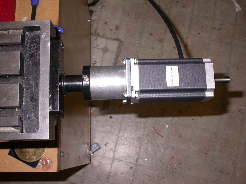
Photo 8: X-axis motor fitted
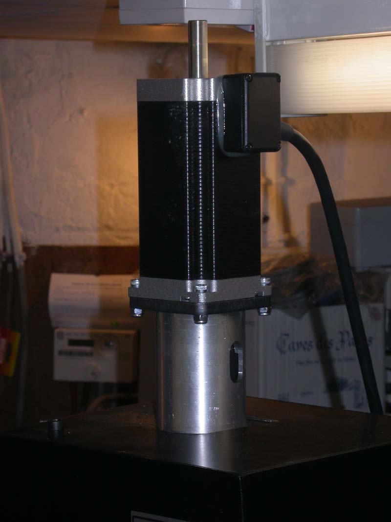
Photo 9: Z-axis motor fitted
The motors Dick used were approximately 1.63 Nm holding torque, NEMA 23 size motors. As he indicated in his article, he could have used smaller motors than these, but chose a greater margin of safety by using larger ones.
Arc Eurotrade has recently been selling two sizes of NEMA 23 stepper motor of Chinese origin; one that is very similar in size and performance to the ones Dick used, and another that is capable of generating about 50% more torque. I wanted to try these out, partly out of interest to see what kind of quality they were, and partly because they are relatively very cheap compared with other sources of stepper motors. Because I was not using the 2:1 reduction drive, and because these motors were an unknown quantity, I decided to use the larger ones, but as I already had one of the smaller ones, it would be possible to do some comparison tests later on
Similarly, Arc have been selling two sizes of stepper drive, one rated at 3A and 40V; the other at 7.8A and 80V. I had used the larger drives already as an auxiliary driver for a rotary axis, so decided to use these for the X3 drive system. I had the makings of a 74V, 6A power supply to hand, which seemed about right to drive the system. This proved to be considerable overkill, both in terms of motor size and driver size, but more of that later.
The power supply is a very simple linear power supply, similar to Dick's design, but delivering a somewhat higher voltage. The torroidal transformer I used has two secondary coils rated at 25V AC, 6A (i.e., a 300 VA rated transformer); by connecting these in series, it delivers 50V AC at 6A. When rectified using a bridge rectifier and smoothed with a 10,000 microfarad capacitor, this gives a no-load supply voltage of a shade under 74V, and its current rating will be correspondingly lower.
At fist sight, this sounds like a rather lightweight supply, as the motors are rated at 2.5A/phase; 3 motors, 2 phases each, 2.5A/phase, sounds more like a requirement for 15A. However, a number of factors come into play here:
- In a modern microstepping "chopper" drive, such as the ones I planned to use, the full current is never applied to both phases at the same time. What the drive does is to adjust the current in each phase to generate the ?microstep? positions; when stepped continuously, the current in each phase reasonably accurately follows a pair of Sine waves 90 degrees out of phase with each other. So when one coil is at its max current, the other is not, and vice versa; it turns out that the absolute maximum total current drawn by a single motor is 1.414 times its rated phase current in a microstepping drive.
- Chopper drives are in effect switch-mode power supplies; they take a high supply voltage, much higher than the motor nominally needs to drive the rated current through its windings, and by sensing the current in the motor windings, they switch off the supply when the rated current is reached, switching it back on when the motor current decays again below the rated level. In the setup I am using, the 74V supply is 10 times as much as is needed to drive the rated current through the motor windings; hence, the average current drawn from the supply will be very much less than the motor spec would lead you to believe. I tested this out using a 25 volt bench supply that had a current meter fitted, using one of my DivisionMaster controllers to drive one of the motors; even under significant load, I could not persuade the drive to draw more than 1.5A.
- Stepper current increases with the mechanical load that the motor experiences; however, in a practical CNC system, there are rarely more than two (the X and Y axis) motors that are heavily loaded at the same time, and often, when doing straight line moves, it is only one motor that takes the strain. So again, the average current drain that the supply will have to source is less than you would expect from the motor specs.
The whole of the power supply fits neatly inside the cavity at the base of the X3's rear housing; the top half of this housing contains the electronics for the spindle motor speed control. Photo 10 shows the mains on/off rocker switch, fuse holder, and IEC socket fitted into the bottom of this sheet steel housing; Photo 11 shows the inside view with a pair of wires and connectors hanging down ready to connect mains to the transformer, mounted on the case back plate (Photo 12) along with the rectifier and capacitor. The smoothed DC is fed through the back plate into the controller mounting box, which is "piggy backed" onto the case back plate, as shown in Photo 13.
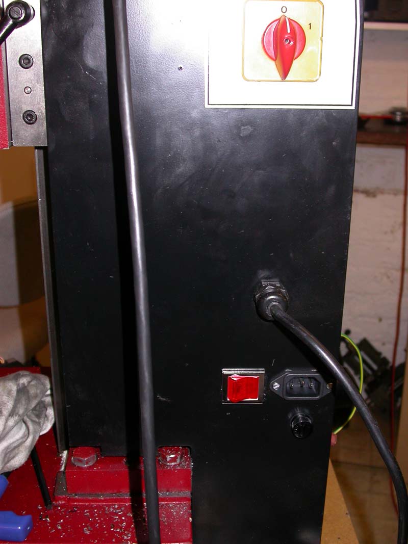
Photo 10: Rocker switch, fuse, and IEC socket fitted for stepper supply
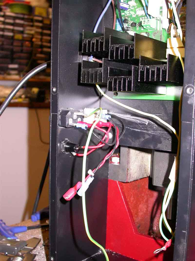
Photo 11: Internal wiring for mains to stepper supply
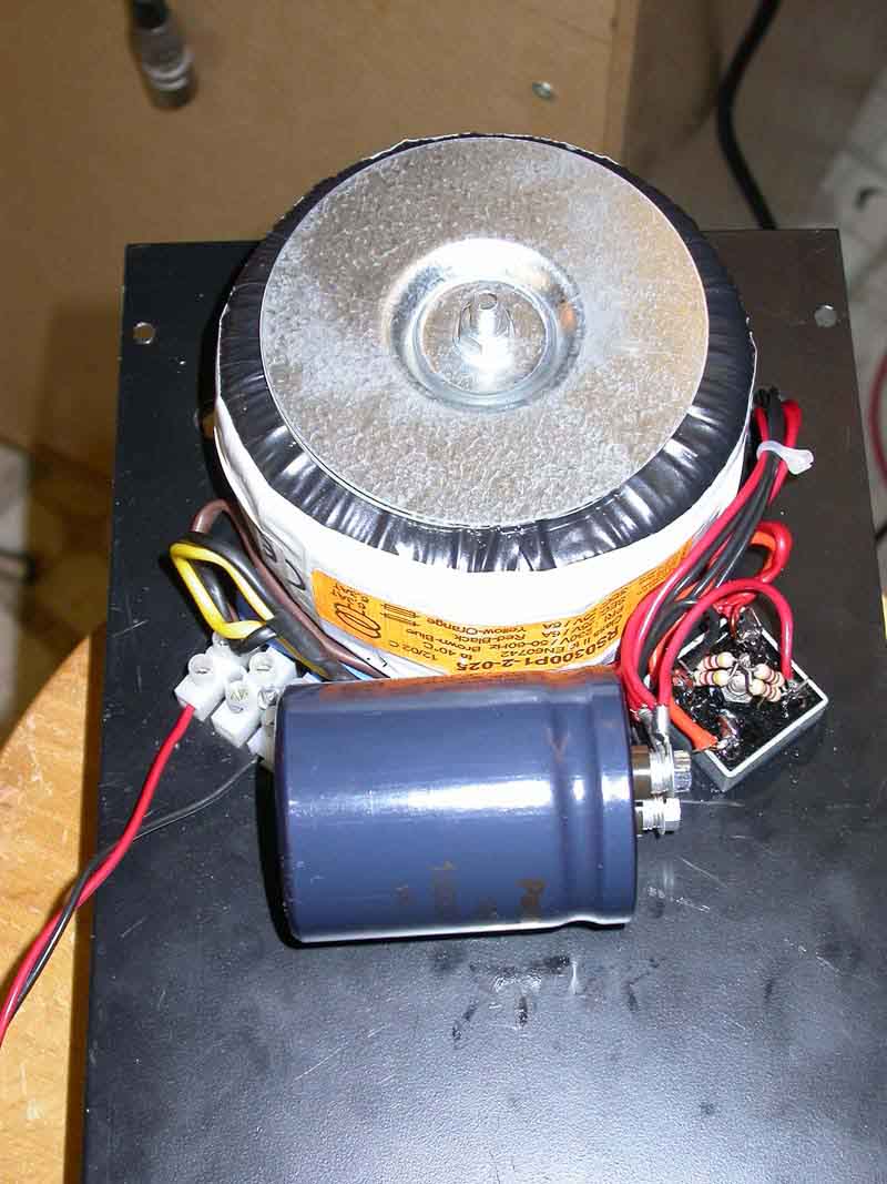
Photo 12: Stepper supply mounted on back plate of the mill
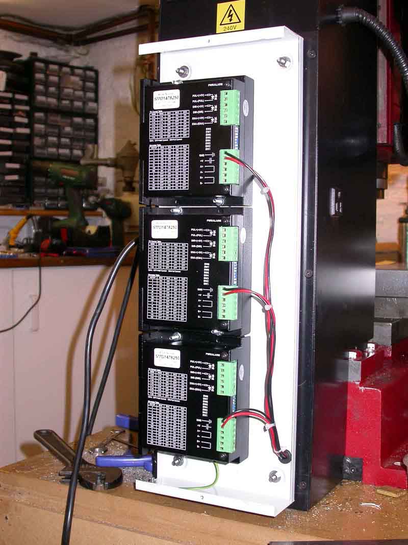
Photo 13: Three axis drive in box mounted on the back plate
As can be seen, I have only built a 3 axis drive system; as I have a variety of 4th axis devices, all of which can be driven by my DivisionMaster controllers, a built in 4th axis drive was somewhat unnecessary for me.
One potential disadvantage with the larger drivers sourced from Arc is that they are quite large when mounted flat on their backs. It wasn't till somewhat later that I realised that they could also be mounted vertically; however, by that time I had already decided on a mounting solution based on a long metal case, part number 215-5310 sourced from RS components (Radiospares as was). This case is slightly smaller than the large back plate of the mill, and when attached to the backplate (Photo 13) there is room to access the 6 screws that hold the backplate in position.
The case is slightly shallower than it needs to be to allow space for the wiring into the two connectors on each stepper driver, so I turned this into a virtue by fitting 8mm deep stand-offs so the lid, when fitted, leaves an 8mm gap at the top and the bottom, allowing free flow of air through the case. In use, with a setting of 2.5A on the drivers, they do get warm (but not hot) using this arrangement, despite their ample heatsinks; if you were to use higher current ratings than this I would advise fitting a fan to force cool the drivers.
Photo 13 shows the drivers mounted in place with the 74V supply connections wired up. Note that I have "star wired" these from the smoothing capacitor of the power supply - it is not a good idea to "daisy-chain" the supply wiring from one drive to the next, as current drawn by a drive that is nearer to the power supply can effectively "starve" drives of current lower down the chain. In fact, if the wiring from the power supply to the drive is likely to exceed about a foot (300mm), it is advisable to fit local reservoir capacitors of 470 microfarads across the supply terminals of each drive - these must have a voltage rating at least 25% higher than the supply voltage.
Photo 14 shows the remainder of the wiring "harness" fitted into the lid. I use 4-pin XLR plugs and sockets for the motor connections; these are robust and have a locking mechanism that prevents accidental removal, and their pins are rated for 15A each, so they are perfect for this job. Most importantly, the solder "buckets" on the pins are big enough to easily take heavy gauge cable.
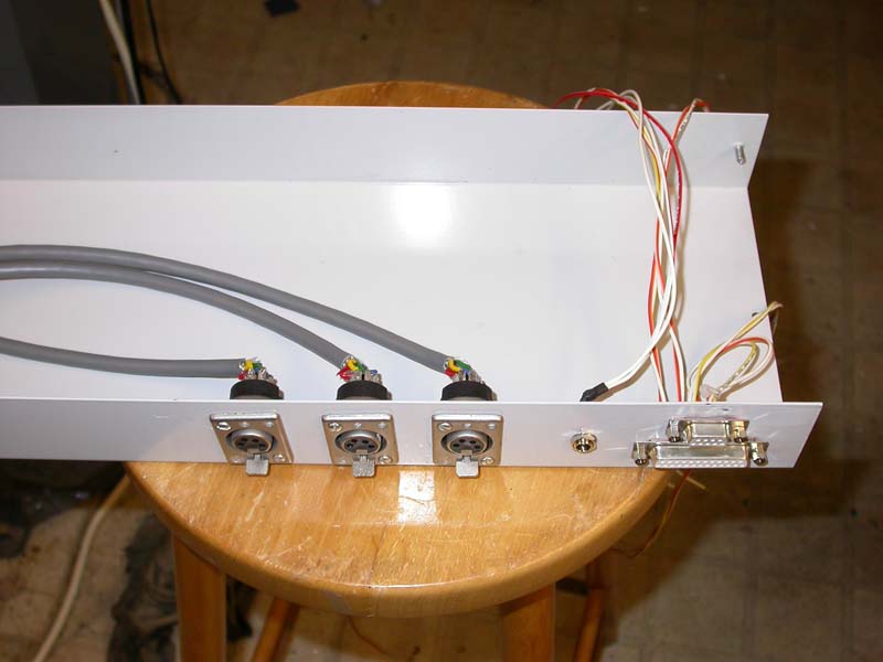
Photo 14: XLR sockets and D-type sockets
There are three sockets fitted to the case. The first is a female D25 socket that carries the step and direction signals for the drives, and which can also carry limit switch signals if need be (a later project here!). I have used a fairly conventional connection plan for this socket, as follows:
Pin Signal
2 X axis Step
3 X axis Direction
4 Y axis Step
5 Y axis Direction
6 Z axis Step
7 Z axis Direction
8 A axis Step
9 A axis Direction
The A axis signals are wired directly into pins 4 (Step) and 9 (Direction) of a D9 female connector; this is to allow me to connect a DivisionMaster controller into the system to use as the 4th axis drive.
This arrangement allows me to drive the mill directly from a PC parallel port, using (for example) Mach 2/Mach 3 or Turbo CNC software, which are popular and inexpensive "control" software packages. However, as the Arc drives are opto-isolated, a "common" 5-volt signal is needed, which must originate from the computer that generates the step and direction signals. This is provided for via a small 2.1mm power supply socket that can be seen between the XLR and D-type sockets in the photo. From this socket, the 5V is taken individually to each drive and connected to the "+" signal connections for step and direction, the D-type pins (2 through 7) are connected to the "-" signal connections.
Deriving the 5V from the PC is straightforward if the PC has USB sockets - Photo 15 shows a USB cable that I have modified for this purpose. I simply chopped off the device end of the cable and wired the +5V wire (conveniently, this is the red one) into the centre pin of a 2.1mm power plug to match the socket in the driver case.
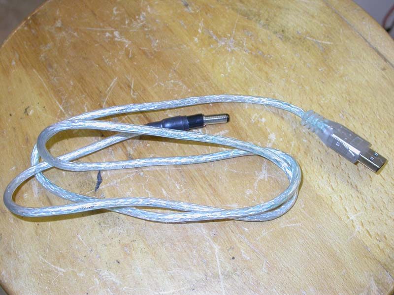
Photo 15: Modified USB cable for 5V supply
Photo 16 shows the case cover fitted, with the motors plugged in. This photo shows the one "deliberate error" that I managed to make during the conversion - if I had mounted the drivers the other way up (connectors on the left), and shifted them to the right hand side of the driver box, the motor sockets would have ended up on the left (looking at the back of the machine), which would have been right for the X axis motor. This way, I ended up with the X motor cable a little on the short side, so a spot of rewiring is needed to make this work properly.
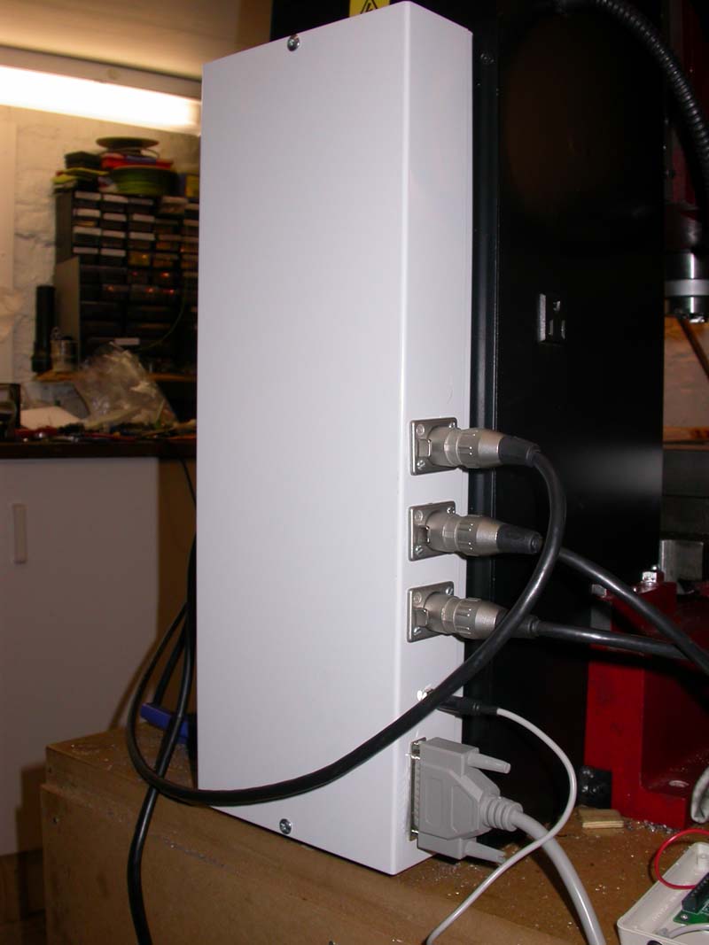
Photo 16: Drive system in place
The D25 connector arrangement means that I can easily swap between software that can drive the mill directly from the parallel port (Mach 2, Mach 3, Turbo CNC, etc.) and other packages, such as DeskCNC, that use some form of external processor to generate the step pulses. I already had a DeskCNC controller board and software license, so my initial experiments were with this. I mounted the DeskCNC controller board in a simple plastic box, with its D9 serial port connector and power LED poking out one side, and a D25 female connector, power supply in cable, and 5V reference out cable poking out of the other side, as seen in Photo 17. The wiring from the DeskCNC controller to the D25 is as described above - X Step to Pin 2, etc. The power supply for the controller was derived from a spare "wall-wart" power supply. The only other wiring for the DeskCNC controller is to ground the "Emergency Stop" (EStop) line; eventually I will make proper use of the Estop and the limit switch connections available on the board in order to produce a more complete and safer conversion, but in order to get up and running this is all that is needed.
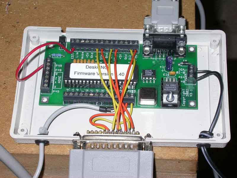
Photo 17: Desk CNC control board
Some of the more modern PCs use parallel ports that are not capable of generating the full 5V signals needed to drive the stepper drives' opto isolators; if this is the case, and you plan to use software that uses the parallel port, then there are a number of "breakout boards" available that will buffer the PC's output signals and generate proper 5V signals as outputs. At some point, I plan to try using Mach 3 to drive this mill, in which case I will probably make up a similar box with a breakout board in place of the deskCNC controller, using one of the boards available from CNC4PC .
Setting up DeskCNC is pretty straightforward, as described in Dick's article. The main difference is that I am using 8 microsteps per step; the Arc drivers can be set for a variety of different microstep settings, from half-stepping through to 256 microsteps per step. In reality, there is absolutely no point in using more than 8 microsteps per step with these drivers (the Geckos that Dick used are 10 microsteps); a larger number of microsteps simply means that the PC or external driver card just has to work harder to get the same motor speeds, and the improvement in smoothness of drive is marginal beyond this level.
The version of the DeskCNC controller that I have (the Mk 1 version) can generate a pulse train up to about 45,000 steps per second. With my setup, which needs 800 step pulses to move 1mm (8 microsteps per step, 200 steps per rev of the motor, so 1600 microsteps per rev, with a 2mm screw pitch), this would equate to a table movement of 3,375 mm/minute, which is shifting pretty fast. My starting point for initial tests was to set up the DeskCNC software for a maximum speed of 40,000 steps/sec (3,000 mm/min); I found that the larger motors were being over-driven at this step rate and were missing steps, whereas the smaller motor (fitted to the Y axis, which actually has a harder job to do than the X, as it carries the weight of both axes) was perfectly happy running at these speeds. This is not unexpected; as both motors have the same current rating, the larger motor is a higher voltage device, which means that it will lose torque at lower step rates than the smaller motor, although at low step rates, it will generate more torque. So, having reduced the step rate to 30,000 steps/sec, which still generates a very respectable 2250 mm/min max speed, all motors seem to operate well within their capability.
These results very much bear out the comments on motor sizing in Dick's article; if I was repeating this exercise, I would probably go with Arc's smaller NEMA 23 sized motors, if for no other reason than that they are physically shorter than the others and therefore stick out less.
In my very initial tests on the machine, before completing the drive circuitry, I used one of my DivisionMaster controllers, which has a 24V supply and a max current rating of 2A/phase, to drive one of the axes, just to see whether all was working OK. Even with this lightweight drive system, which was down-rating the available motor torque to 80% of the motor's capability because of the lower phase current, I was able to achieve table movements of around a metre a minute. Consequently, if it is desirable to do a "budget" CNC conversion on one of these mills, the smaller (40V, 3A/phase) drivers and the smaller motors would still deliver a respectable performance.
At one point, I was driving the Z axis up and down, and leant on the top of the head to see just what kind of force the drive system was generating. Admittedly, it was difficult to put much weight on the head due to its height and the need to hold the jog button down at the same time; however, the fact that the motor showed no signs of stress led me to do some more definitive tests.
I had a small spring balance, calibrated to 30 Kilos, to hand, so I attached this between the head and the table, as shown in Photo 18. The motor happily drove the Z axis up to beyond the end of the 30 Kilo scale, without breaking a sweat. Encouraged by this result, I looked around for a tougher test. Photo 19 shows the result - a set of bathroom scales resting on the bed, with the head bearing down on them via a piece of timber and an old cable reel, inserted as a spacer. I chickened out when the indicated weight on the scales reached 130 Kilos; not because I was concerned for the mill, but because I didn't want to have to replace a crushed set of scales!
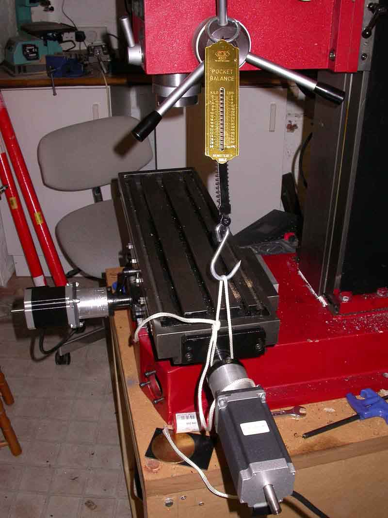
Photo 18: The easy test
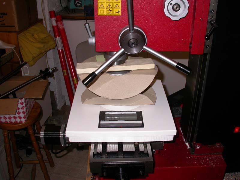
Photo 19: Attempting to crush the bathroom scales!
So, the conclusion from this is that the setup described is capable not only of generating rapid movements at respectable speeds, but also capable of generating forces in excess of 130 kilos at the tool tip. I strongly suspect that this is more than sufficient for most requirements on a mill this size, and perfectly capable of ruining the larger sizes of cutter that might be used if driven too hard for the spindle speeds and materials in use.
The performance observed with this conversion has convinced me of one thing - many people approaching CNC conversions go way overboard when it comes to choosing the stepper motors that they will use. I am (or should I say, was) probably just as guilty of that as anyone else - I have to admit that at one point I was seriously considering using NEMA 34 motors rated at about twice to three times the torque of these NEMA 23 motors. Clearly, if my setup is capable of generating the kinds of forces that I have measured, extra torque is not a requirement; the other side effect of using NEMA 34 motors would have been a reduction in the top speed obtainable. Hence, using the bigger motors would have been a waste of time and money.
Certainly one of the reasons that this setup is relatively easy to drive, and hence, can use smaller motors, is the decision to use ballscrews, which give an efficiency advantage of 2-3 times over using ACME screws; however, I suspect that even if I had decided to drive the original ACME screws, the motors I used would have given an acceptable result.
Now it is probably time to stop fiddling with the conversion and start making some chips fly; however, as mentioned above, my eventual plan is to see how Mach 3 compares as a control system for the mill. Expect a further article when I have had time to try it out!
DivisionMaster is no longer in production.
Arc Euro Trade http://www.arceurotrade.co.uk
RS components Ltd https://uk.rs-online.com/
Mach 2 and Mach 3 can be downloaded from http://www.artofcnc.ca/
Turbo CNC can be downloaded from http://www.dakeng.com/turbo.htm
DeskCNC products can be obtained from http://www.deskcnc.com
CNC4PC's website is http://www.cnc4pc.com/
X3 Mill conversion to CNC
© Tony Jeffree 2006
All Rights Reserved
Email me at this address...
website ({at}) jeffree.co.uk
Return to Model Engineering Activities page...