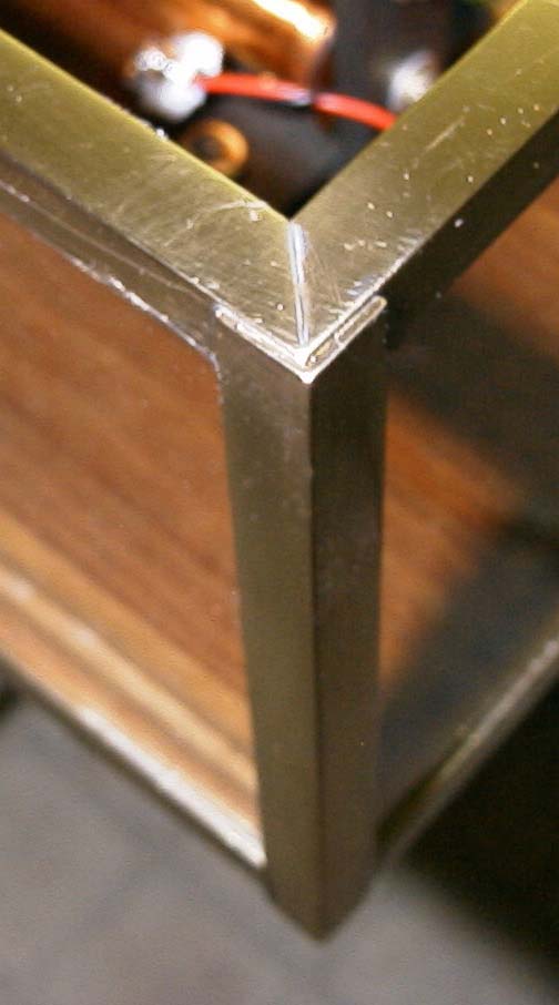
Photo 1: Case corner detail.
Copyright © Tony Jeffree, 28th March 2001. All rights reserved.
As noted at the end of my article on engraving a chapter ring for my 3/4 Second Pendulum Clock, completing the work on the movement and chapter ring caused me to start thinking about making a suitable case. The constructional series suggested a simple backboard and an acrylic sheet hood; I have never managed to produce an acceptable result when using acrylic sheet, so I fancied building something using glass instead.
My initial thoughts were to attack some of the store of reclaimed hardwood in my garage; I had some teak from old chemistry lab bench-tops, about 1" thick and reasonably flat, that showed promise. One of these pieces yielded a suitable back board; I then set about converting the remaining piece into 1/2" square section strips, with the intention of routing out retaining grooves in these strips to enable them to act as corner supports for a predominantly glass case. At least, that was the theory. It rapidly became apparent that attempting to cut about 8 metres of 2 mm wide retaining grooves was a non-starter, surpassed only by the difficulty of accurately machining the 1/2" square strips with the equipment to hand. Back to the drawing board.
In search of inspiration, I took a trip to the local B&Q to see whether their stock of pre-machined hardwood strips would yield a solution. I didn't find anything suitable in wood, but I did find a stock of 10mm X 10mm brass angle and 6mm X 6mm brass U-channel in metre lengths, which looked promising. I could see that the angle could be used to form the frame to carry the glass sides of the case, while the U-channel could be used as edging for a glass front. I purchased 5 lengths of the angle and 3 of the U-channel, and set about designing the case.
In the diagrams and the description that follows, I have deliberately been fairly sparse with dimensions; this design was very much a based on making use of materials that I had to hand, which may not necessarily match those available to other constructors. Nothing about this design is in any sense "hard and fast", other than the blindingly obvious point that the case has to be large enough to accommodate the particular movement concerned! In particular, I have shortened the pendulum rod on my clock relative to the original dimensions in the constructional series, to reduce the length of the threaded rod below the bob, and I have used a chapter ring that is just under 6" diameter, slightly smaller than the pierced chapter ring described in the series. I would therefore caution potential constructors to check that the dimensions quoted below make sense when applied to their own version of the clock movement, and to make adjustments accordingly.
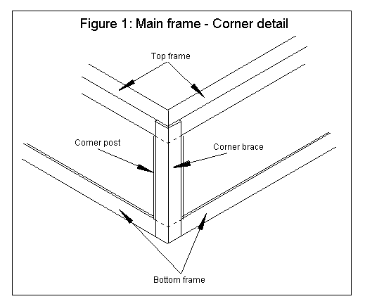
I spent a while deciding on the right construction for the frame. The brass angle is only about 1mm thick, so I quickly realized that "butt" joints and mitres on their own were not going to produce a robust enough structure, unless I brazed the joints, which I didn't think would be all that easy to achieve in such thin material without using elaborate clamping arrangements. Eventually, I went for the approach illustrated in Figure 1 and Photo 1. The brass angle forms an open box, with external dimensions 8"wide, 32" long and 5.5" deep, constructed from a top and bottom frame each made from four lengths of angle, mitred at each corner. These two frames are separated by four corner posts that are 5.5" minus 2cm long; finally, the four corner posts, each 5.5" long, are used to reinforce what would otherwise be very weak butt joints. The whole structure is held together with soft solder joints.
Photo 1: Case corner detail.
The main frame sits on top of the backboard, in a 1/2" deep rebate cut to the size of the opening at the bottom of the frame (approximately 7.2" by 31.2"). The backboard was cut smaller than the main frame, about 7.5" by 31.5", so that the frame appears to stand out from the wall slightly, while still giving enough overlap to allow the frame to be firmly attached to the board. The frame has a glazed top, bottom and sides; I used 2mm glass cut to size by my local picture framer, but there is no reason why thicker material should not be used.
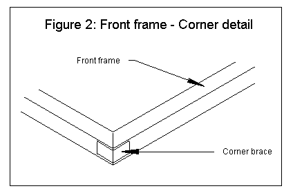
The U-channel was mitred to form a frame for a 2mm thick glass front door, with external dimensions approximately 7.6" by 31.6". The corners of the door frame are reinforced by braces made by cutting 4mm lengths of the brass angle (see Figure 2 and Photo 2).
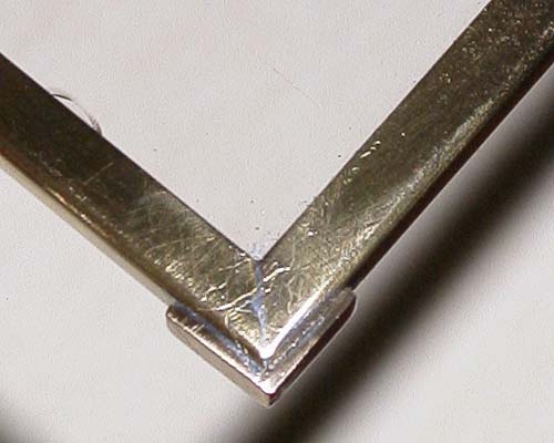
Photo 2: Door corner detail.
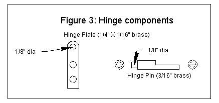
The glass door is attached to the main frame by means of simple "pin and plate" hinges top and bottom (see Figure 3 and Photo 3). The two pivot pins are made from 3/16" brass rod, with a 1/8" diameter spigot turned on one end, and a flat cut to half the diameter to allow the pin to be attached to the corner brace, so that the pin is in line with the long edge of the front frame. The two hinge plates are simple strips of 1/4" by 1/16" brass; one end is rounded, and is drilled to be a comfortable running fit on the reduced diameter of the hinge pins; the other holes are clearance holes for 6BA screws that will attach the plates to the corner braces. The final dimensions of the hinge components are determined during construction - see later.
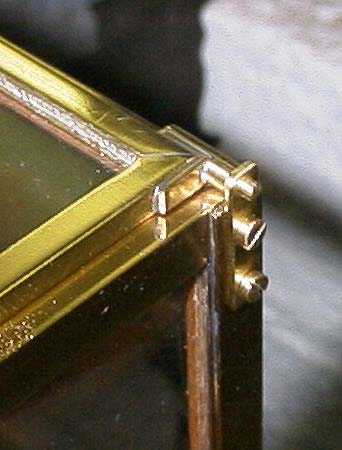
Photo 3: Hinge detail.
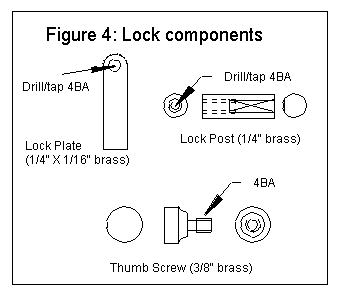
The remaining components form a simple lock (see Figure 4 and Photo 4). The lock plate is a piece of 1/4" by 1/16" brass, drilled and tapped 4BA; this will be attached at right angles to one of the long sides of the door frame, and will carry the thumb screw. The thumb screw is formed from a short length of 3/8" diameter brass rod. About a 3/8" length of the rod is turned down to 4BA diameter and threaded to the shoulder, and then about the last 3/32" up to the shoulder is turned right down to slightly less than the core diameter of the thread. The head of the thumbscrew is completed by a small radiused undercut, conveniently done with a small button tool if you have one to hand. The threaded portion of the thumb screw can thus screw all the way through the threaded hole in the lock plate, leaving it "captive" in the threaded hole of the plate when the door is open. When the door is closed, the threaded end screws into the lock post, a piece of 1/4" diameter brass rod, drilled and tapped axially 4BA. The lock post is attached half way along one of the long sides of the top frame, and protrudes from the side by slightly less than the thickness of the door, ensuring that the door will be firmly closed when the screw is fully home, but that the lock plate will not be put under too much stress by the screw.
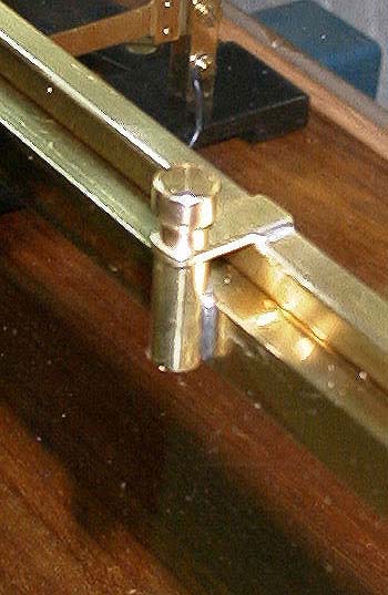
Photo 4: Door lock detail.
The backboard was cut to size, and marked out to take the clock movement and electromagnet. Holes drilled behind the bottom component of the steel clock frame, and behind the magnet, allow most of the wiring to be neatly concealed in a channel routed into the back of the board. I fitted a miniature plug and socket to the electromagnet, allowing it to be removed from the case without disturbing the hidden wiring. A further hole was drilled below the electromagnet assembly to allow the battery leads to be brought into the case. A countersunk hole at each corner of the backboard provides for the mounting screws that will hold the clock on the wall. Once all holes were drilled, the board was finished with a few coats of quick drying varnish. All mounting screws were solid brass slot-head screws, with heads brought to a reasonable polish before lacquering.
The various components of the main frame were cut next. The cuts needed for the frame components are easily and accurately done if you have access to a fine slitting saw (see photo 5); I used a Peatol lathe to do the cutting of all the frame components, using the vertical milling slide and milling vice to hold the brass angle stock in place. The photo shows one of the mitres being cut, with the vertical slide angled at 45 degrees to the direction of cut. The brass angle that I bought did not have a particularly good surface finish, so I did a lot of sanding work on these components prior to assembly, to minimise the final sanding and polishing that would be needed on the unsupported frame. This preparation work is well worth the effort, as the frame is much more difficult to work on once it has been constructed.
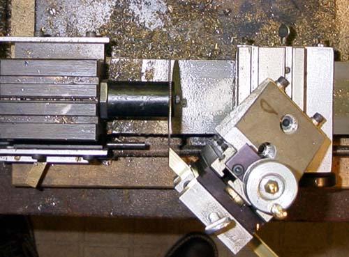
Photo 5: Mitring brass angle strip using a slitting saw on a Peatol (Taig) lathe.
The simplest construction sequence for the main frame is to build up the bottom frame, by soldering the corner posts and braces in place, and then to solder the top frame components in place afterwards. Whatever sequence you choose, the biggest problem is holding four components in the right position long enough to flood solder into the joint. I had acquired a number of surgical clamps of various shapes and sizes (they look like a cross between a pair of needle nosed pliers and a pair of scissors, with a ratchet arrangement in the handles to clamp them in position); these proved ideal for this task. Mini "Mole" grips and small engineers' clamps also proved to be useful. Slight adjustments can be made to ensure that the corner posts and frames are square, by carefully re-heating the joint. Once the corner posts are in place, the top frame components are clamped and soldered in place. The frame can then be attached to the backboard with Epoxy adhesive, and any excess solder or adhesive around the joints cleaned up. The lock post can be soldered into place at this point; it has a 1 cm long flat filed on it to give a good area of solder joint with the brass angle.
There is one potential drawback with gluing the frame permanently in place on the backboard; access to the movement is then restricted by the sides of the case, so any adjustment to the action of the Operating Lever and its Operating Pawl will have to be done prior to fitting the movement into the case. If easier access is felt to be desirable, it would be a simple matter to attach the frame to the board with screws as an alternative to glue.
Next step was to cut the components for the door frame. One of the long sides is soldered to the two short sides, using the corner braces; this then allows the correct length of the hinge pins to be determined. The objective here is that when the pins are in place, the distance between the shoulders on the two pins should be a hair less than the length of the top frame. The hinge pins are now turned to size, the flats cut, and the pins soldered in position on the corner braces. You now have a 3-sided door frame with one long side open and two hinge pins in place. The hinge plates can now be positioned on the main frame corner braces and spotted through; these should be positioned so that the door will be central on the top of the main frame. The corner braces are drilled and tapped 6BA for mounting screws. These screws should be cut so that they do not protrude beyond the inner surface of the corner when screwed into position. With the hinge plates in position, check that the door hinges nicely; if necessary, the mounting holes in the plates can be elongated to provide final adjustment.
Four 2mm glass sheets, that will form the top, bottom and sides of the case, can now be attached to the inside surfaces of the main frame. I chose to use rapid setting Epoxy adhesive for this, holding the glass in place with wooden braces while the glue was setting. I found that the long sides of the top frame had "sagged" a little during construction; careful adjustment when attaching the glass allowed me to straighten these components while the glue was still fluid, making a flat surface for the door to mate with. Take care also to grease the ends of the hinge plate mounting screws and leave them in place while gluing the glass sides in, to make sure that the screws do not become permanently stuck or the screw holes filled with glue. Once the glass was in place, I attached hardwood "quadrant" section strips to all of the inside corners of the frame, primarily to tone down the interior of the case so that it did not draw the eye away from the movement, but also to add a little reinforcement. Epoxy adhesive will do well for this, as will clear silicone bath sealant - a little known all-purpose adhesive! Once all is set, any excess adhesive can be removed from the joints using a sharp knife and a scraper - I used the kind of scraper sold for removing paint from windows, modified to allow it to operate right up to the edge of the glass.
The door construction is completed by sliding the glass in place and then soldering the second long edge in place, with its corner braces. I used a small blowtorch for all of the soldering; with care, these last joints can be made with the glass in place, without cracking the glass. The door can then be fitted to its hinges to mark out the position of the lock plate, and to cut it to length. The lock plate was then soldered in position on the door frame. Finally, the gap between the U-channel and the glass was filled with Epoxy adhesive; this should be done with the door in its hinges, and with the thumbscrew screwed home, to ensure that it all still fits properly after the glue is set. I used a relatively new (to me at least) grade of epoxy adhesive that is extremely quick setting - 90 seconds or so - and is almost colourless; an alternative, albeit much slower setting, would be clear silicone bath sealant. Again, the excess glue can be removed with knife and scraper.
All the metal components were finished using increasingly fine wet & dry paper and metal polish, and a coat of horological lacquer to prevent tarnishing. The finished case, with movement in place, can be seen in Photo 6.
The ultimate finishing touch is to conceal the rather unsightly plastic battery holder and its lead inside a brass box, attached to the backboard just below the magnet assembly. The battery holder I have used carries 2 "D" cells; this will need a box that is about 3" X 3" X 1.5" to allow the batteries to be completely concealed. I leave this last piece of construction as an exercise to the reader - mostly because I haven't got around to doing this last piece of work myself yet!
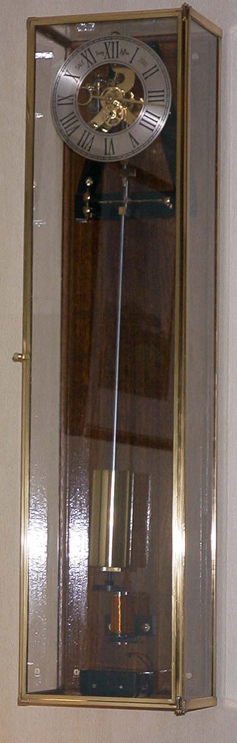
Photo 6: The finished case with movement fited and running.
A Case for the 3/4 second Pendulum Clock
© Tony Jeffree 2001
All Rights Reserved
Email me at this address...
website ({at}) jeffree.co.uk
Return to Model Engineering Activities page...