Copyright © Tony Jeffree, 13 December 2000. All rights reserved.
In order to complete my construction of John Wilding's 3/4-second Pendulum Clock (serialized in Model Engineer circa 1998), I needed to obtain or make a suitable dial. The clock itself has been running happily for some while, but lack of a dial has impeded my enthusiasm for completing the project, building a case, and so on.
I must confess that I was rather too lazy to follow his design completely and attempt a pierced chapter ring, and the commercially available examples looked a little "cheap", so I decided that I would have a go at producing an engraved a chapter ring using my Taig MicroMill 200 CNC mill (Ref. 1). This is not quite as straightforward a problem as it might seem. The mill's table travel is not great enough in the Y direction to make it possible to machine over the entire surface of a 6" diameter workpiece, so the problem got shelved (along with the completion of the clock) for some while until I had worked through the possible alternative machining strategies, and also freed up enough time to think about them.
My first thought was to engrave the dial in two halves. This would fix the Y-travel problem, but I was rather concerned about accuracy of registration when I came to reverse the piece to engrave the second half. While potentially do-able, I felt that the number of failed attempts before the registration problem got fixed would be just too disheartening.
The alternative was to make use of a rotary 4th axis. I had previously built a CNC dividing head for the mill some while before, based on a modified Taig (Peatol) lathe headstock; however, this was designed to be used with its axis parallel to the X-axis, and what I really needed was a rotary table with the axis of rotation parallel to the Z-axis. I toyed with the idea of designing and building a stepper-driven rotary table, but decided that this was probably overkill.
As with a lot of these problems, the solution became "obvious" after it had been festering in my brain for some weeks, and one evening, I noticed my shiny new Sherline (Ref. 2) 90-degree angle plate sitting on the workbench. This angle plate is about the same width, and slightly shorter, than the Taig milling table, and would clearly provide a simple means of converting the dividing head to a "rotary table".
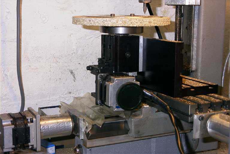
The final setup is seen in the following photo. The Sherline angle plate is clamped to the Taig mill table with its vertical face aligned with the front edge of the table. The CNC dividing head is clamped to the vertical face of the angle table by means of holes drilled and tapped in the table to match the T-bolts (UNF 10-32). This gives just enough clearance for full Y travel without the back end of the dividing head and its motor assembly fouling the Y-axis ways or its motor. Happily, this arrangement also leaves enough room in the Z axis to mount a standard Taig face plate on the dividing head's spindle nose to form the table surface.
A 7" diameter disk of particle board, with a 7" disc of 1/8" thick engraving brass sheet attached to it with double sided tape, was attached to a face plate and trued up on my ML7, giving the surface of the brass a light skim to make it nice and flat. The particle board/brass sandwich was then bolted onto the Taig faceplate and screwed onto the nose of the dividing head.
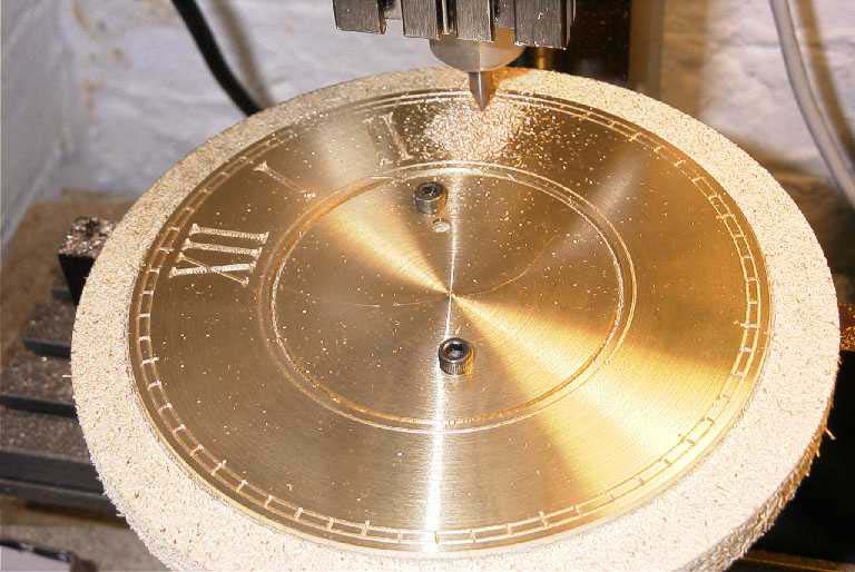
The cutter used was a 1/4" diameter, double-ended solid carbide engraving cutter with a 60 degree V-tip and a tip diameter of about 20 thou.
The next photo shows the chapter ring part way through the engraving process.
For the hour/minute marks and the three circular grooves, the CNC programming was achieved using AutoSketch to draw the the toolpaths in linear form. I used the rotary table as a substitute X-axis, simply swapping the rotary table motor for the X-axis motor. With the setup I used, a linear movement of 3.6" translates into a rotary movement of 360 degrees, so a 3.6" movement in X gives a complete rotation of the table. The three rings therefore appear as straight moves in X (i.e., three straight lines, left to right, on the Autosketch drawing), and the minute and hour marks appear as straight moves in Y. The AutoSketch drawing for these toolpaths can be seen below. The lines in X are slightly over length (3.75") to ensure that there is a smooth join; the hour marks are separated by 0.3" on the drawing, and the minute marks by 0.06".
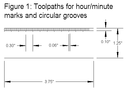
Another two straight moves in X allowed me to clean up the chapter ring to 6" diameter, and to cut out the central hole, still using the V-tipped cutter, but cutting to the full depth of the metal rather than the 30 thou or so used for the engraving marks.
This is probably the least satisfactory part of the end result, as the purist clockmakers amongst us will probably observe that I have not strictly adhered to traditional form for this. A traditional clock face that uses Roman numerals would have been engraved or painted by hand, and would have been laid out such that, at any chosen hour position:
In other words, imagine two circles drawn on the chapter ring to denote the positions of the tops and bottoms of each character. Taking the 3 o'clock position as an example, the middle stroke of the roman numeral would be exactly on a radius drawn from the centre of the ring, but its two partners would be parallel to it (and therefore, not on a radius). All three strokes would extend the full distance between the two drawn circles. The horizontal strokes at the top and bottom of each numeral would be arc segments of the two drawn circles.
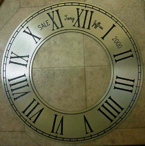
Ideally, in order to produce this traditional form, I would have painstakingly drawn out the various strokes required in linear format (i.e., between the horizontal lines on Figure 1) such that any vertical strokes that were not to be on radii were angled appropriately such that when I machined the toolpaths using the rotary X axis, everything would come out in the right place. While this is perfectly do-able, I decided to take a slightly less satisfactory, but rather simpler, and very much quicker approach. SuperCam (Ref. 3), which is the software package that drives the Taig mill, has a simple CAD front end that includes the ability to engrave text. Conveniently, one of its in-built fonts is a version of Times Roman that looked promising; the thick strokes are formed by three parallel cuts and the thin ones by a single cut. Engraving the numerals was straightforward using this feature; rotate the table to the first hour position using the rotary X axis, switch back to linear X for the engraving, rotate to the next hour position, and so on. The end result (as can be seen in the second photo) is numerals that conform to the traditional requirements in so far as the vertical strokes are parallel rather than all radial, but do not conform to the requirement that the tops and tails should be arc at a constant radius. The alternative would have been to use rotary moves, in which case, the verticals would not have been parallel. I judged that the latter would not have looked quite right, so opted for the former. Perhaps for the next clock I will bite the bullet and draw it all out properly.
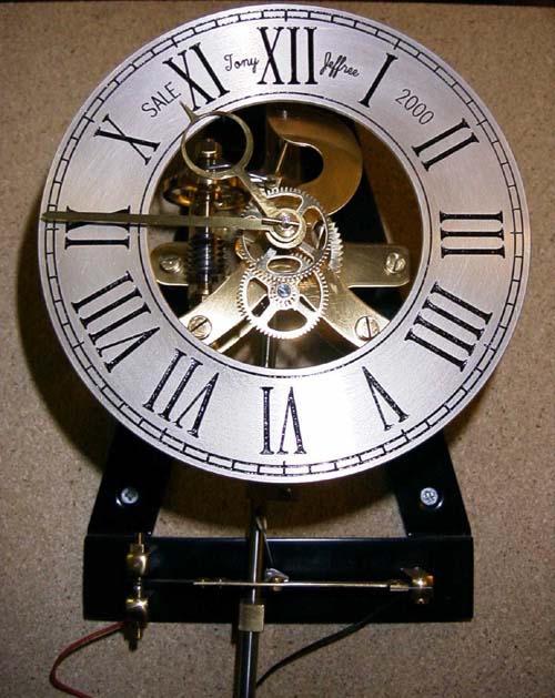
The next photo shows the finished chapter ring. The final engraving work was to add location, maker and date; these were engraved using rotary X moves and the SuperCam in-built fonts.
The engraved ring was then removed from the table and the engraving marks cleaned up to de-burr and remove swarf, and the engraved marks filled in with black sealing wax. It was then returned to the Myford face plate for finishing with fine wet & dry paper to give the right "grain" to the surface, then silvered using commercially obtained silvering salts, and lacquered, as per the instructions in John Wilding's series. All in all, apart from the slight deviation from traditional numeral form, a very satisfactory end result.
Having successfully completed the chapter ring and made the pillars to attach the ring to the movement, I had no remaining excuse not to finish the final polishing and lacquering of the clock's components. I had made use of the CNC Mill to ease the work involved in crossing out the various wheels, and had cut the profile of the front and back plates under CNC control. I had already done most of the fling necessary to clean up the edges of the parts, so all that was left to be done was to remove the remaining file marks and bring the surfaces to a decent state of polish. I had planned to use wet & dry paper, emery sticks, metal polish etc. to do this, but in the process of unearthing the necessary materials, I came across a sample pack of an abrasive material known as Micro-Mesh (Ref. 4). I had obtained the samples from Crafts for 4 Seasons before they went out of business, and had put them in the drawer with my stocks of wet & dry paper without investigating their properties.
MicroMesh comes in a variety of forms; the samples I had resemble emery cloth, but the surface is formed from abrasive particles embedded in a latex matrix. The literature accompanying the samples says that the cushioned surface allows the abrasive particles to align themselves with the surface of the work, and the result is a much finer and more even scratch pattern than would be expected from the same grade of conventional abrasive. Suffice it to say that the sample pack contained a wide enough range of grades of abrasive to allow me to obtain an acceptably high polish on the brass components of the clock without the need for the use of any other polishing compounds. At the time of writing the original article, Micro-Mesh products were distributed in the UK by P.W. Products but they appear to have sold the MicroMesh business to a new UK distributor, DEP Fabrications (Ref. 5), but I do not know whether they offer sample packs.
The fnished clock movement, with chapter ring attached can be seen in the next photo. The majority of the brass components of the movement (front and back plates, wheels, hands, and count wheel bracket) were also machined with the help of SuperCam and the Taig mill.
As can be seen, the movement is attached to a sheet of chipboard that I have been using for testing and setting up; the next step was to build a suitable case.
Ref. 1: The Taig MicroMill 2000 CNC Mill is distributed by Quantum CNC (Europe) Ltd, Wall End House, Moor Lane, Coleorton, Leicestershire, LE67 8FQ, U.K. Tel. 01530 834376. Website: http://www.quantumcnc.co.uk/
Taig equipment is manufactured by Taig Tools, 12419 E. Nightingale Lane, Chandler, Arizona 85249, U.S.A. Tel: (602) 895-6978. Website: http://www.taigtools.com/
Ref. 2: Sherline equipment can be obtained through Millhill Supplies, 66/68 The Street, Crowmarsh Gifford, Nr Wallingford, Oxon, OX10 8ES, U.K. Tel: 01491 838653.
Sherline equipment is manufactured by Sherline products, Inc., 3235 Executive Ridge, Vista, California 92083-8527, U.S.A. Tel: 760-727-5857. Website: http://www.sherline.com
Ref. 3: SuperCam software is obtainable from Super Tech & associates, 2433 East Waltann Lane #1, P.O. Box 30729, Phoenix, Arizona 85046-0729, U.S.A.Tel: 602-867-1755 . FAX: 602-867-1426. E-mail: info@super-tech.com Website: http://www.super-tech.com
Ref. 4: Micro-Mesh products are manufactured by Micro-Surface, Inc., 1217 West Third Street, Wilton, IA 52778, U.S.A. Tel: 1-800-225-3006. Fax: 319-732-3390. Website: http://www.micro-surface.com
Ref. 5: DEP Fabrications, Unit 33, Cam Centre, Hitchin, Herts, SG4 OTW U.K. Tel: 01462 441414. Fax: 01462 442110. www.depfabrications.com Email: enquiries@depfabrications.com
A CNC-Engraved Chapter Ring for a 3/4 second Pendulum Clock
© Tony Jeffree 2000
All Rights Reserved
Email me at this address...
website ({at}) jeffree.co.uk
Return to Model Engineering Activities page...