Copyright © Tony Jeffree, 18th February 2000. All rights reserved.
The Taig micro lathe (distributed in the UK by Peatol Machine Tools) is a popular and versatile small machine, albeit with some limitations. Probably the two most significant amongst these are the absence of a leadscrew and change wheels for fine feed and threading, and the absence of dividing accessories. There is an article elsewhere on this website describing the addition of a leadscrew and associated equipment. This article addresses the second problem; how to add division capability to the lathe. As will be seen in the description that follows, the result is not just another dividing head or dividing attachment. Rather, it offers a comprehensive set of facilities for performing a wide range of dividing tasks in the Taig lathe, or in conjunction with its big brother, the Taig mill (distributed in the UK by Quantum CNC). The construction sequence described below also generates a useful milling spindle and a boring bar holder as accidental, added bonuses.
A few years ago, I built a simple dividing head for the Taig lathe. This Mk I design was based on a 1MT drill chuck arbor that I had turned down to a plain shank, and mounted at centre height in a frame fabricated from 2" aluminium angle. The Mk I dividing head has proved to be a useful accessory since then; however, as it is limited to the use of a drill chuck as the workholding device, I had planned to develop a Mk II device that would provide a wider range of workholding options. I had originally intended the Mk II dividing head to be based around a No. 1 Morse taper spindle that would have provided the desired wide range of workholding options. However, while mulling over the possibilities, I was struck by the thought that ideally the head would allow the full range of standard Taig workholding devices (collets, 3 and 4-jaw chucks, faceplate, drill chuck arbors, etc.) to be used. Clearly this would involve designing the dividing head spindle to have the same nose as the Taig headstock, complete with through hole and internal taper; it would then take all the standard Taig tooling including any special arbors or attachments that might have been machined for it. This train of thought led naturally to the idea that I could simplify the construction considerably if I used a complete Taig headstock as the basis of the design and modified it to suit the purpose. It turns out that Taig will supply any of the components of the lathe individually, so a complete headstock was duly purchased for the project. (Actually, what I did was to treat my lathe to a new headstock and modify the old one, but that is a minor detail.)
Other advantages of basing the design around a modified headstock also became apparent as I thought it through. In addition to its use as a dividing head, it would be possible to remove the worm drive, division plates, etc. and fit the standard Taig drive pulley, thus allowing its use as a cross-slide or vertical-slide mounted milling spindle. Equally, any dividing attachments could readily be attached to the lathe headstock, having removed the lathe's drive pulley, giving the possibility of using the dividing capability directly in the lathe itself.
As with my previous design, I chose a 30:1 ratio for the main worm drive, using standard parts from HPC Gears. This choice of ratio was largely dictated by the physical dimensions that I was working within; I wanted the head to be capable of cross-slide mounting in the lathe with its spindle at centre height, and there is approximately 1¼" between the spindle and the surface of the cross slide. Limiting the height of the dividing head was also desirable given that I wanted to be able to use the head in the Taig CNC mill as well, as it is a bench-top mill with relatively limited Z-axis travel. The final choice was a 30T, 20DP phosphor bronze worm wheel and single-start steel worm (HPC part numbers M20-30 and W20-1 respectively). This seemed to provide a drive that fitted the space available, and was also substantial enough to take the 5/8" bore required to fit it to the Taig spindle. The choice of drive ratio was also affected by some of the considerations described in my previous article; with a 30:1 ratio, it is easy to cut a 12-hole circle, and from that, to cut a 360-degree protractor. Once you have a protractor fitted to the dividing head, it is then a simple matter to cut any of the other hole circles that you may decide are useful.
As I seemed to be "on a roll" with the way the design was coming together, I decided that I might as well do the thing properly and add the option of compound indexing, in a similar manner to that offered by the celebrated George Thomas "Versatile Dividing Head" design. I felt that providing the compound head with a theoretical positioning resolution of 1/1000th of a degree (as is the case with the original VDH design) would be over-egging it just ever so slightly. Hence, I settled for an order of magnitude less on the positioning resolution, which should still be more than enough for most purposes, and is probably still rather better than my own machining ability would justify! Hence, my design for compound division uses a supplementary 30:1 worm drive to position the division plate, and 40 divisions on the graduated thimble fitted to the secondary worm shaft, giving positioning of the output shaft to a theoretical resolution of 1/100th of a degree. The ultimate positioning ability of a device built to this design will, in reality, be limited by the accuracy of the individual components and of the overall construction, so whether positioning to this accuracy is really possible is another matter altogether. As this secondary worm drive will never be required to take any load, I chose to use a Delrin worm drive from HPC's 32DP range (HPC part numbers ZPM32-30 and ZW32-1 respectively).
The dreaded "feature creep" continued when I started to think about using the dividing head with my Taig CNC mill, which also makes use of the same headstock as the Taig lathe. I realised that it would not be terribly hard to make an adapter that would allow a NEMA 23 stepper motor to be mounted on the dividing head, allowing its use as a 4th axis under CNC control. Visions of "hands off" milling of clock gears made this a very attractive proposition. However, for convenience in CNC operation with the Taig mill software, the worm drive ratio needs to be chosen such that it will render an integral number of motor steps per degree of rotation. A 30:1 ratio combined with a 400 steps/rev motor doesn't achieve this goal; 72:1 seems to be a more usual ratio for these devices (see Peter Rawlinson's design in issue 56 of MEW; also, commercial rotary tables for small CNC mills appear to use this ratio). This results in 80 steps per degree - comparable to the performance of the compound division capability described above. For this option, I used a modified 32DP, 72 tooth phosphor bronze wheel and a steel single-start steel worm (HPC part numbers PM32-72 and W32-1 respectively).
Further features of this design include the ability to perform direct dividing by attaching division plates directly to the spindle in place of the worm drive. Although not described here, raising blocks could easily be added for machining diameters in excess of 2.5". Similarly, tailstock support can be added for situations where it is necessary to machine long parts.
Finally, wherever possible, I have designed the components so that the head can be assembled with either "handedness". When working on the lathe cross-slide, it is often convenient to have the spindle nose pointing left with the division plate facing the operator. However, when using the components with the lathe headstock, it would be more natural to have the division plate facing you with the spindle nose pointing right. Converting between the two orientations can be achieved very rapidly.
So, in summary, the design as described offers a wide variety of interesting possibilities from which the reader can pick and mix to suit particular needs:
Of course, the usual comments apply at this point; the materials, dimensions, etc., shown in this design are in many cases simply a reflection of the materials I had to hand, and can therefore be modified and substituted to suit the contents of your stock and scrap box. A major reason for the use of the Taig headstock as a basis for this project was to maintain compatibility with the Taig work holding attachments and to allow the division components to be attached to the headstock of a Taig lathe. However, this design will no doubt be usable with other lathes and mills, perhaps with appropriate modifications to centre height and T-bolt spacing (within the constraints of the geometry of the headstock and its spindle assembly). As the chucks, drill chuck arbor, collet closer and collets for the Taig lathe are all very reasonably priced, it would be relatively inexpensive to equip the head with a range of workholding accessories if it were to be used in conjunction with a different lathe or mill.
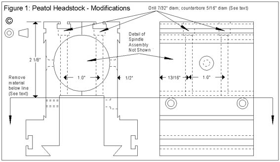
NOTE: These modifications to the headstock may need to be adjusted if a different centre height for the finished dividing head is desired. If the head is to be used only on a mill table, it may be appropriate to use the headstock unmodified; as supplied by Taig it comes with a mounting plate (the same width and bevel as the Taig lathe bed) for mounting on other machines. In this case, the standard Taig lathe tailstock could be used, mounted on a similar mounting plate, to provide tailstock support on the mill table.
The Taig headstock consists of a pair of aluminium extrusions that hold a steel spindle carried in a pair of substantial 4cm OD ball races, with a steel spacer tube between the two races. The lower part of these extrusions form "legs" that carry dovetail slots; these locate the headstock onto the lathe bed. Two 10-32 UNF countersunk screws hold the spindle in position between the two extrusions; a further two 10-32 UNF cap screws pinch the dovetail slots onto the lathe bed.
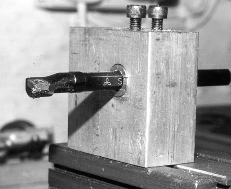
Taking your courage in both hands, remove the 4 screws, separate the extrusions from the spindle assembly, and remove the lower ends of the "legs" with a hacksaw, as shown in Figure 1. This will remove the dovetail slots and the holes for the cap screws, leaving a pair of "feet" a few millimetres long below the bearing housings.
Reassemble the extrusions onto the spindle, ensuring that the two halves end up with their outer surfaces parallel. I chose to use a spot of Locktite bearing retainer on the extrusions to hold everything nicely in place; this was partly because I was modifying the old headstock from my lathe, and a certain amount of wear was visible in the front bearing housing. The two "feet" can now be milled to their final height, which should leave about a millimetre of the foot below the housing; this operation is shown in the photo below.
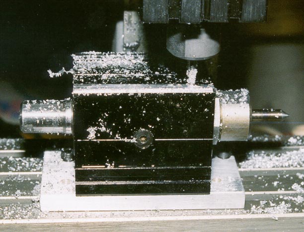
The final dimension after machining is far from critical at this point, as you get a second bite at the problem later on when the base plate (Figure 2) is added and machined to give the right final centre height. The requirement here is to create a nice flat base onto which the base plate can be attached. I found that the most convenient way to mount the headstock for this operation was to use the T-slots in the top surface of the headstock extrusions as a means of attaching a 3" by 2" mounting plate with countersunk T-bolts. The assembly can then be fixed to milling table (or vertical slide) with further T-bolts through the mounting plate.
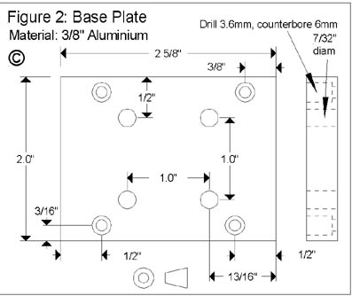
The base plate is made from a piece of 3/8" by 2" aluminium, 2 5/8" long; it is fixed to the newly milled feet on the bottom of the headstock by four 4BA cap head screws. Ideally, the holes for these screws and the threaded holes in the feet should be drilled together. Clamp the base plate in position on the base of the spindle assembly and drill through both items with a 3.1mm (4BA tapping) drill. The holes in the base plate can then be opened out to 3.6mm (4BA clearance), and counterbored 6mm to bury the cap heads well below the surface. Tap the holes in the feet, then fix the base plate in position with the cap head screws. Note that the hole positions are not symmetrical; this is simply to ensure that should the base plate be removed for any reason, it will always go back the same way round, although there is not likely to be very much reason to do this.
The remaining four holes in the base plate are to allow T-bolts to pass through the base; these holes are arranged in a 1" square to match the spacing of the T-slots on the Taig lathe and mill. By now you will have spotted that these T-bolts must pass right through the body of the truncated headstock. The easiest way to drill these holes is by mounting the spindle/base plate assembly upside down, as it was for milling the feet, and to drill through from the base using a 7/32" drill. Careful marking out is needed here; the objective is to have the T-bolt holes straddle the spindle, and to emerge in the middle of the T-slots in the upper surface of the headstock housing. In the process, the drill will partly pass through the steel spacer that separates the two bearings, as well as the aluminium extrusions, but will not penetrate into the bore or damage the spindle itself. This drilling operation provides ample opportunity for the drill to deflect, so gentle drilling and good lubrication is the rule. The assembly is then reversed, and the four holes counterbored 5/16" diameter to a sufficient depth to allow a 10-32 UNF cap screw head to sit below the bottom of the T-slot.
By the way, if the arrangement described and illustrated above is used to hold the spindle down while drilling these holes (i.e., using a clamping plate T-bolted onto the top surface of the spindle), be careful to ensure that the T-bolts used to hold the spindle onto the plate do not coincide with the expected points of emergence of the holes you are drilling. When I drilled these holes, I did not realise that these two T-bolts were precisely below two of the holes. In drilling the last two holes, the drill neatly took off the ends of the T-bolts, after which the spindle was no longer attached to the milling table. Thankfully I realised what was about to happen in time to switch off the mill, but it was a very close call!
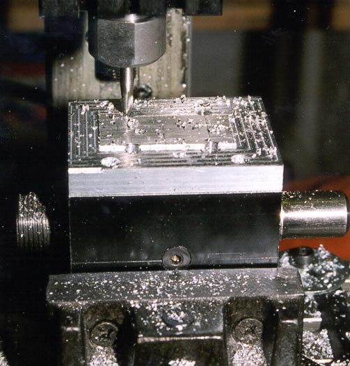
The assembly can then be returned to the mill or vertical slide to skim the base plate; this can be seen in progress below.
The plan here is to fix the spindle height of the dividing head such that it will be on centre height when fixed to the cross slide. Nominally, centre height over the cross slide is 1 ¼". However, it is worth doing some careful measuring to check the height on your own lathe. It is also worth taking care in the set-up to ensure that the final machined base is actually parallel to the axis of the spindle, and square to the sides of the spindle housing.
The T-bolt holes needed to secure the spindle to the cross-slide or milling table are rather long. You will need 2 1/4" 10-32 UNF T-bolts to fix the spindle to the Taig lathe cross-slide or 2 ½" bolts to fix it to the Taig mill table (which has the same 1" T-slot spacing as the lathe, but the slots are deeper.) I found that Emkay Supplies could source 2 ½" 10-32 bolts by special order, but unfortunately, at a special price, too. 2" is the longest stocked length I could find elsewhere; of course this may be a lesser problem for readers in the USA.
The result thus far is the first usable product of this project - a milling spindle that can be mounted on the lathe cross slide or vertical slide (or indeed, on a milling table if you can dream up an application for this!). The Taig lathe pulley sets and drive belts can be pressed into service for this purpose, along with a suitable fractional horsepower motor. I have not attempted to describe mounting arrangements for this application, as motor mountings and dimensions will vary. However, there is plenty of scope, given the availability of the two T-slots on the top of the spindle housing, to provide a mounting that can allow a motor to be rapidly attached and detached as needed. The short drive belts supplied for the Taig Mill are probably the most appropriate for this application; using a Taig pulley set, this combination gives approximately 3.8" between the axes of the milling spindle and the motor shaft.
I pondered long and hard as to the best approach for providing a locking mechanism for the spindle. Clearly, if I was building the spindle and housing from scratch, the obvious approach would be to use some kind of clamp between the two bearings, as seen in the recent design by Harold Hall, published in MEW issues 53 and 54. However, as I did not relish the thought of dismantling the pre-loaded spindle assembly in order to modify its steel spacer, this was not a real option. Remaining options were to fit a brake shoe at the nose (turning down the 1" AF hex nut behind the nose thread to form a brake drum), or at the rear of the spindle, directly behind the rear bearing. I opted for the latter approach, as it is extremely useful to be able to use a spanner on the spindle when tightening the collet closer.
The rear end of the spindle poses problems of a different kind. There is a circlip that ensures that the spindle cannot escape the clutches of the bearings; this protrudes slightly less than 2mm proud of the aluminium housing. The rear bearing itself protrudes somewhat less than this also. So the brake shoe has to be offset from the rear surface of the housing by 2mm. The spindle itself is 17mm diameter at the point where the circlip retains it in the bearing; it then rapidly changes to 5/8" diameter for the remainder of its length. The brake shoe needs to be bored with both 17mm and 5/8" diameters, so that it can straddle the change in diameters of the spindle. This allows the available space at the rear of the spindle to be used to its best advantage, and in particular, also leaves sufficient room for the worm drive to be attached. These factors explain the rather curious shape of the brake shoe, shown in Figure 3.
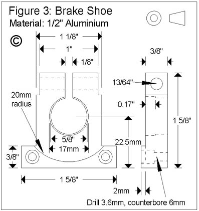
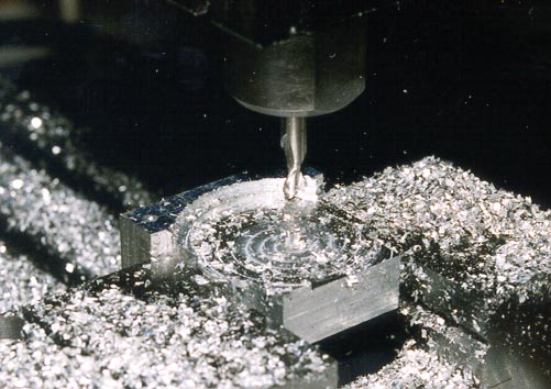
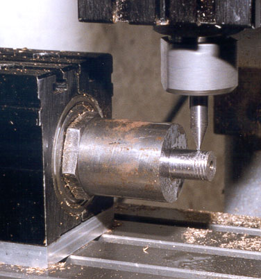
The shoe is made from a piece of ½" thick aluminium, 1 5/8" square. I had the luxury of being able to machine the shoe entirely using milling and drilling operations in the Taig CNC mill. Boring 17mm diameter holes with a 5/32" end mill is a lot of fun with such a machine; this operation can be seen in progress below. Needless to say, the lathe, vertical slide and 4-jaw chuck are equally appropriate tools for the operations required here.
The final shoe will be 3/8" thick, with an extra 2mm for the foot to offset it from the circlip and rear bearing. Having trued up the piece to 1 5/8" square, it is necessary to mill or turn one face to reduce the overall thickness to 0.454" (3/8" plus 2mm). The foot is then formed by removing a further 2mm of material on a 20mm radius centred 22.5mm from one edge, and 13/16" from the adjacent edges. The piece is then through bored 5/8" diameter, on the same centre, followed by boring 17mm diameter to 0.17" below the surface. The profile of the piece is then cut as shown in Figure 3, and a hacksaw or slitting saw used to cut through to form the split clamp. Drill the mounting holes as shown, and counterbore them to allow the 4BA cap head mounting screws to be buried below the surface. Finally, drill the 3/16" hole for the pinch bolt. Note that the 3/8" square cutouts allow the pinch bolt (Figure 4) to be inserted in either direction through the clamping hole; this is one of the "ambidextrous" design features mentioned earlier. The cutout serves to prevent the 3/8" square pinch nut from turning - use a standard Taig lathe square T-nut for this purpose, or make one up from 1/8" X 3/8" flat stock.
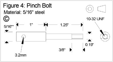
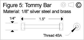
The pinch bolt (Figure 4) is made from a 2.25" length of 5/16" diameter mild steel. Turn down 1.25" of its length to .19" diameter and thread the last 3/8" 10-32 UNF. Cross-drill ¼" from the other end 3.2mm. The Tommy bar (Figure 5) is a 1.5" length of 1/8" diameter silver steel rod; thread each end with a 4BA die for about 1/8". Strictly speaking, 1/8" is too small for 4BA threading, but it will take enough of a thread for this purpose. Fit a 4BA brass nut to each end and turn them down to remove the flats. Pass the Tommy bar through the hole in the pinch bolt and fix the end caps in place with a drop of Superglue.
The pinch bolt can then be fitted through the hole in the brake shoe, with a steel washer under the shoulder and a square 10-32 UNF nut (the type used as T-nuts on the Taig lathe) at the threaded end. As mentioned above, the bolt can be fitted from either direction, depending upon the desired "handedness" of the indexing components.
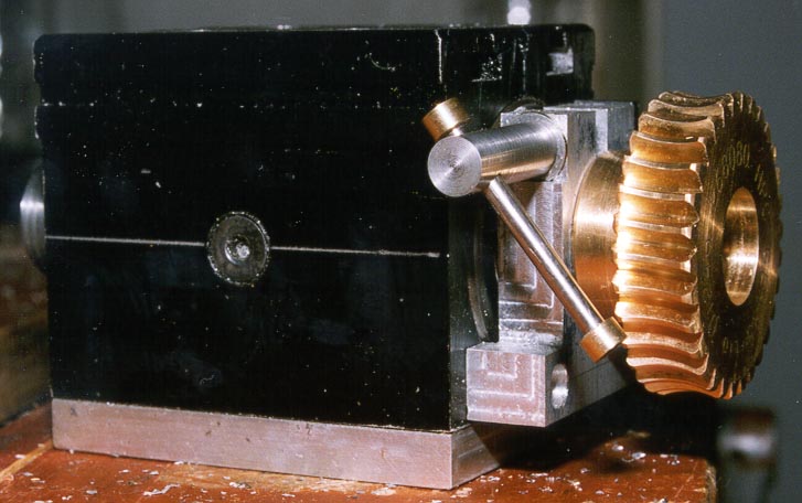
The shoe can now be fitted in place on the rear surface of the spindle housing, with its foot and mounting screws at the bottom. Clamp the shoe onto the shaft using the pinch bolt and nut. Spot through the mounting holes, drill 3.1mm (4BA tapping), and tap 4BA. The shoe can now be screwed into position. Note that if you plan to use the dividing components on the lathe headstock, this operation will need to be repeated on the rear of the lathe headstock. The next photo shows the completed brake shoe assembly, and the 30T worm wheel, fixed in position on the rear of the spindle assembly.
This component is shown in Figure 6; it serves as a universal mount for the various dividing components. This plate is designed to fit at the tail end of the spindle, using the T-slots in the top of the aluminium shell - hence the two 3/16" holes in the base plate to take 10-32 UNF T-bolts. The two semicircular notches reduce the degree to which the plate obstructs the rear pair of T-bolts that pass through the headstock. If preferred, these could be elongated to merge with the 3/16" holes to form a slot; the only disadvantage with this alternative is that the T-bolts for the mounting plate are then no longer "captive".
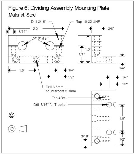
The mounting plate is fabricated from 2" lengths of ½" X ¼" and 1" X 3/8" steel bar; these should preferably be clamped together while milled or filed to length in order to ensure that the lengths are exactly the same. However, this is only a cosmetic issue, as the length is not terribly critical. The lower 3 holes in the 3/8" thick vertical plate need to line up with the 4BA tapped holes in the ¼" thick horizontal plate. The intent here is that the two plates are clamped together using 4BA socket head screws, and the counterboring allows the heads of the bolts to end up below the surface of the plate, leaving the rear surface of the plate unobstructed. The usual approach of careful marking out, spotting through holes etc., should be sufficient to ensure that these line up. Those of you that have a mill available (or even a cross vice with graduated leadscrews) will find this straightforward as the hole positions can be dialled in from a reference edge. Of course, one of the great advantages of CNC is that this kind of drilling operation can be performed simply, repeatably and with great accuracy; despite drilling these two components independently using the Taig CNC mill, I found that they fitted together perfectly.
The two 5/16" holes should be drilled undersize and reamed to size; these need to be a close fit with the 5/16" steel bars that will be used to hold the various dividing components. The vertical holes for the 10-32 UNF pinch bolts are drilled last, after the horizontal saw slits have been cut. Drill to depth with a 10-32 UNF tapping drill (4.1mm) and then follow up with a 3/16" drill to the level of the saw cut. The lower holes can then be tapped UNF 10-32. If you feel particularly energetic, the pinch bolts can be replaced by variants on the pinch bolt and Tommy bar shown in Figures 4 and 5; however, as these bolts are likely to be used relatively infrequently, this may not be felt worth the additional effort involved.
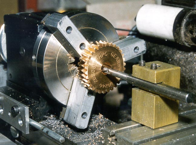
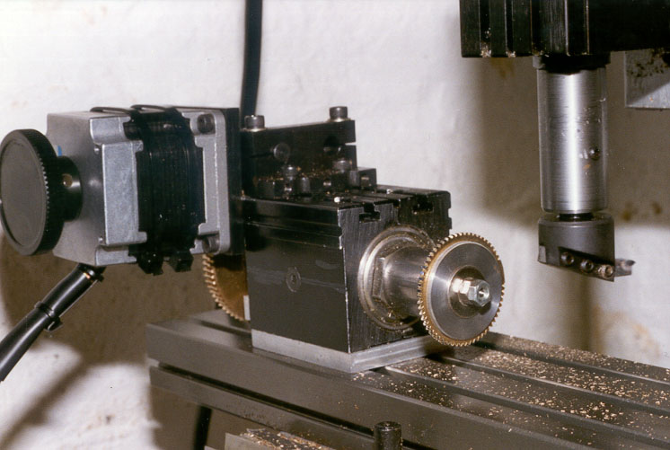
The 20DP worm wheel as supplied by HPC Gears (see above) comes with a 3/8" diameter bore. This needs to be increased to 5/8" diameter to fit the end of the spindle. HPC will modify bore diameters for an additional fee, but this can also be achieved in the lathe. Grip the 1" diameter boss in the 4-jaw and centre it carefully using a dial gauge. Alternatively, the boss can be held in the 3-jaw, if it is sufficiently accurate, or if you are prepared to bore out the Taig chuck's soft jaws to hold the boss spot on. The bore can then be opened out using a suitable boring bar - this can be seen in progress in the next photo, using a 1/4" boring bar fitted with a Sumitomo titanium carbide insert.
The wheel will need a grub screw; drill and tap the boss 10-32 UNF to take a ¼" long hex socket head set screw. The wheel is fitted "boss first" onto the spindle and located with the grub screw. The wheel will overhang the end of the spindle by about ¼"; leave a small gap between the boss and the brake shoe so that there is no rubbing between these components. I chose to file a flat on the spindle to act as a pad for the grub screw to locate against; I have filed a similar flat on my lathe spindle. This simplifies fitting and removal of the wheel and drive pulley, as the inevitable burrs raised by the grub screw do not then foul the bores.
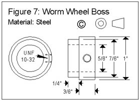
Modifying the 72-tooth worm is slightly more involved; it is supplied either with or without a boss, but the standard boss is less than 5/8" diameter and is therefore of no use in this application. Again, no doubt HPC could make a non-standard wheel for a premium on the price. However, I chose to use the plain version of the gear as a starting point. A boss is cut from a piece of 1" diameter round stock, as shown in Figure 7; a small shoulder is cut for ¼" of the length of the boss (the thickness of the worm wheel), leaving 3/8" at the original diameter. Bore it through at the same setting, to ensure that the 5/8" hole for the spindle bore is concentric. A radial hole is drilled/tapped 10-32 UNF to carry a grub screw as for the 30-tooth wheel. The worm wheel is then chucked, carefully centering its axial hole. I did this by machining a set of soft jaws to hold the wheel safely in the 3-jaw without damaging the teeth, but this could equally be done with a 4-jaw and careful packing of the jaws. Open out the bore in the wheel to give a press fit over the small diameter of the boss; press the wheel into place, using Locktite or Superglue to form a permanent joint.
As with the 20DP wheel, the 32DP wheel is mounted on the spindle with the boss facing the brake shoe. This wheel will also overhang the end of the spindle slightly when in place.
Figures 8, 9 and 10 show the components needed for this. The design is based around the NEMA 23 size of stepper motor; this is a common stepper size for the various small CNC mills, and is the size suggested for Peter Rawlinson's dividing head design. The mounting plate shown in Figure 8 is straightforward, although some of the dimensions are curious to say the least. I have shown the plate as 2.25" square; this is actually slightly larger than the standard measurements for the NEMA 23 mount.
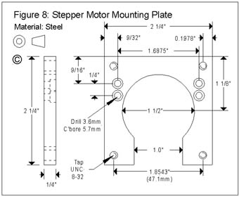
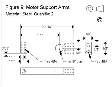
It seems a reasonable assumption that anyone building the stepper motor mount will be using the dividing head with a CNC mill. By far the easiest way to make the motor mount components is therefore to translate the drawings into CNC control files, and then let the machine do the hard part. Otherwise, some very careful marking out is needed to ensure that all fits together nicely. The 5/16" holes carry 5/8" long steel dowels (I used silver steel, but MS would be fine for this), held so that they can fit into the split clamps on the mounting plate, allowing adjustment for backlash and alignment of the worm drive. The provision of a dowel either side of the frame allows the motor to be mounted with either "handedness". You may notice from the later photos that I had originally intended to use a pair of dowels on each arm and to arrange their positions so that the fit of worm and wheel was "spot on". However, I concluded that this was not such a great idea as it is more difficult to mark out accurately and would not allow for any backlash adjustment. The dowels are Locktited into the support arms, and pinned through for additional strength.
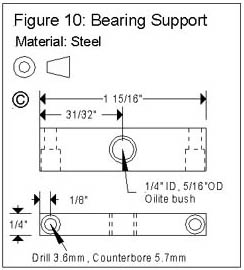
Assembly is fairly obvious; the bearing support screws into the notches in the ends of the motor support arms, and the latter are screwed onto the motor mounting plate. If all is well, the axis of the ¼" bearing will be directly in line with the centre of the 1.5" hole in the mounting plate. Adjustment of the notches in the side arms, or the addition of shim washers between them and the bearing support, can correct any misalignment that may be needed. Fit the worm to the motor shaft before fitting the motor to the mounting plate. A length of ¼" diameter silver steel forms a shaft extension, running in the Oilite bearing; cut this to length and Locktite it in place in the end of the worm once the final position of the worm on the motor shaft has been fixed. The shaft extension should protrude about 3/8" beyond the end of the bearing, to allow a 1/4" ID set screw collar to be attached.
The main purposes of the shaft extension, its bearing, and set screw collar are to support the motor's own bearings and to control end float in the motor shaft. The motor I used has a thrust spring that controls end float to some extent; however, it is possible for transmitted cutting forces to cause this spring to deflect if heavy cuts are being taken, resulting in movement of the workpiece. The set screw collar prevents any such movement. If desired, a second set screw collar can be fitted on the inboard side of the bearing support (Figure 10) to further reduce the transmission of cutting forces to the motor. An additional use of the shaft extension is to provide a means of adding a manual adjustment knob, if the motor you are using is of the single-ended shaft variety. If this is needed, cut the extension over-length and add a manual control knob - the kind found on electrical equipment works just fine if you don't want to make one. My motor had a double-ended shaft, and was already fitted with a manual control knob. The ability to position the worm drive by hand is very useful for setting up the initial position of a component prior to a milling operation, but this should always be done with no power to the motor. The motor can now be mounted on the dividing head with UNC 8-32 cap screws, and the position of the components finally adjusted and tightened. The stepper drive for the dividing head is now complete.
The construction of the various support components for the two worm drives will now be described, followed by the division plates, indexing arm and sector arms. For those that are only interested in building the simple indexing capability (one worm drive), the construction can be simplified and some components omitted; this will be detailed as the description progresses.
Figure 11 shows this component. The carrier has two split clamps that will take 5/16" diameter rods; the left-most of these allows the carrier to be mounted in position, using a 1 ¾" long steel rod held in one of the corresponding clamps on the Dividing Assembly Mounting Plate (Figure 6). The right-most clamp in Figure 11 can be omitted if only one worm drive will be used, as this is used to mount the secondary worm and its carrier.
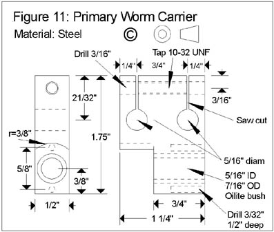
The carrier is fitted with an Oilite bush that forms a bearing for the primary worm shaft. Above and below this bush are marked two 3/32" diameter holes. These carry a pair of locating pins for the Index Plate Boss (Figure 17) which are needed when performing simple indexing without the secondary worm drive fitted; these holes can be omitted in both components if it is intended to leave the secondary drive permanently installed. The 3/8" radius shown above the bush gives clearance for the worm and its set screw, and can be adjusted to suit. The hole for the worm shaft bearing is best drilled/bored in the 4-jaw chuck on the lathe to ensure that it is perpendicular to the face of the carrier; the 3/8" radius cutout can be machined at the same setting. Construction of this component is otherwise straightforward.
The Secondary Worm Carrier and the Worm Lock (Figures 12 and 13) are machined in the following sequence.
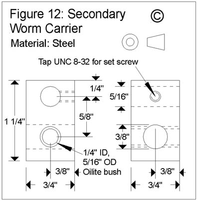
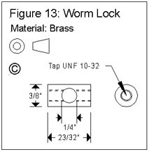
First, cut a length of 3/8" diameter brass rod to 23/32" long (1/32 less than ¾"), drill it axially and tap UNF 10-32 for its entire length. Next, cut a piece of ¾" square section steel bar to length (1 ¼") and carefully mark out the positions of the four holes. My favourite way of doing this is to use the CNC mill with a centre drill fitted as a means of positioning these holes accurately relative to a reference corner, but manual methods are fine too. The bar can now be mounted in the 4-jaw chuck, and accurately centred to bore the 3/8" diameter hole for the worm lock. Remove the work from the chuck - loosen two of the four jaws, to make the next repositioning operation easier. Now temporarily fix the brass rod in the hole with Superglue, taking care to position it so that it is equidistant from each face of the steel bar. If you avoid degreasing these components too thoroughly before gluing, the Superglue will hold them together just fine for the next drilling operation, but will allow the worm lock to be driven out afterwards with a suitable drift. Remount the piece to drill the hole for the Oilite bush; again, carefully centre the hole position. The hole is first drilled ¼" in diameter; this ensures that the hole in the worm lock will be concentric with the secondary worm shaft, regardless of marking out or machining inaccuracies. Remove the piece from the chuck and use a drift to separate the worm lock from the carrier. Clean off any glue residue. The ¼" hole can now be bored out to 5/16" to take an Oilite bush, and the 3/8" hole cleaned out with a drill and reamer to remove the central portion of the bush.
The remaining 5/16" hole and the UNC 8-32 hole for the set screw complete the secondary worm carrier. A 1 ¾" length of 5/16" steel rod is used to connect it to the primary worm carrier; file a flat for the set screw 3/8" from one end. An alternative to the set screw is to fix the rod permanently using Locktite and a steel pin, as there should be no need to remove the rod once fitted.
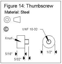
The worm lock can be re-fitted to its hole in the carrier. If all is well, it should be possible to pass a length of ¼" diameter silver steel through the Oilite bush and the worm lock; this will form the shaft for the secondary worm. A 2 ¾" length of silver steel rod is used for the secondary worm shaft; I chose to use Locktite in addition to a set screw to locate the worm on the shaft. The thumbscrew (Figure 14) provides the means of tightening the worm lock; this is straightforward to machine from ½" diameter steel. The thread can be formed by reducing the diameter of the round stock; alternatively, cut a 5/16" length of stock, axially drill/tap 10-32 UNF and Locktite a length of 10-32 studding in place, finishing the threaded portion to 5/32". The latter approach has the advantage that the threads run right up to the shoulder, which makes life simpler. The thumbscrew is finished with a light knurl. Having threaded holes at either end of the worm lock allows the secondary worm to be mounted with either "handedness" on the primary worm carrier. The lock operates very effectively, requiring little finger pressure to lock and unlock the secondary worm. As there is little force on this worm drive in operation, all that is required is to prevent inadvertent re-positioning of the Worm Thimble.
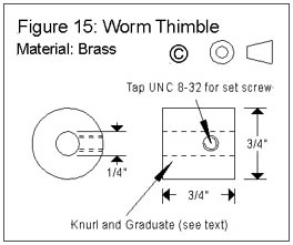
The final operation to perform on the secondary worm carrier is to add witness marks to aid with reading the position of the Worm Thimble. I chose to add these marks to the three possible faces; hence, the thimble position can be read from above the dividing head, or from the side, regardless of the "handedness" with which the components are assembled. I finished the steel components by using a chemical blackening kit; the black surface provides a useful contrast with the witness mark cut into the steel.
The Worm Thimble (Figure 15) is machined from a piece of brass round stock, bored ¼" diameter and cross-drilled for a UNC 8-32 set screw. The surface of the thimble should be knurled at one end and marked with 40 graduations at the other end.
If you have a CNC mill and have made the CNC drive attachment to use with this dividing head, graduating the thimble is a simple job, as seen in the next photo.
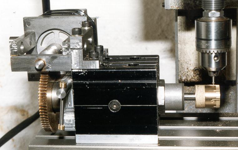
After turning the cylinder to dimensions, the thimble was mounted on a stub of ¼" silver steel rod and held in the dividing head with a ¼" collet. The head was fixed to the milling table, positioned with its axis running in the X direction, and with the spindle directly above, carrying a small engraving cutter. The dividing head's stepper motor was substituted for the Y-axis motor. I had drawn out the graduations and lettering using my PC drawing package as if the graduations were to be cut into a plane surface. Making the Y dimension exactly 3.6" long corresponds to a full 360 degree rotation of the thimble (80 steps per degree is 28800 steps per 360 degrees. The mill software thinks it is driving a linear leadscrew at 400 steps per rev and with a 20 TPI thread. So 28800 steps are equivalent to 72 revs of the "leadscrew" or 3.6" of linear travel). Plugging this drawing into the mill software and setting it going produced a perfectly graduated thimble - major marks every 10 graduations, slightly shorter ones every 5 graduations, and perfect numbering of the tens. At least, it worked perfectly the second time; for the first attempt I had fitted the stepper motor the wrong way round and produced perfect mirror-image numbering, as seen in the photo below.
The thimble can also be graduated using more conventional manual techniques, pressing the partially completed dividing head into service, once a division plate with a circle of holes that is a multiple of 4 has been made (as described below).
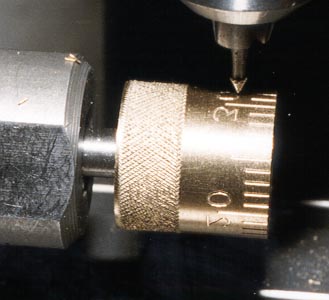
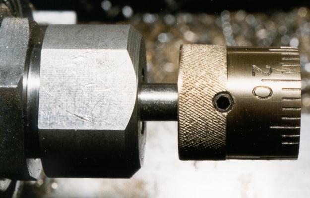
Having engraved the thimble with its graduations and numbers, it is worth making these marks stand out clearly against the metal background. A simple way of achieving this is to fill in the marks with indelible black felt-tip marker ink, allow it to dry, and then carefully remove the excess ink from the high points with very fine emery paper, while the thimble is rotated in the lathe. The finished thimble, with the numbering readable without a mirror this time, can be seen below.
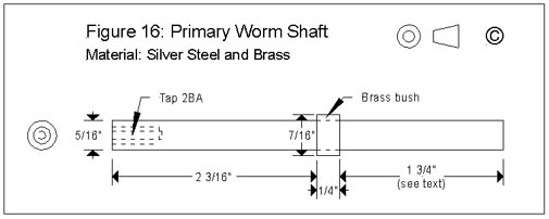
The Primary Worm Shaft is shown in Figure 16. This was cut from silver steel rod; the brass bush shown is Locktited in position. The end with the 2BA threaded hole is passed through the Oilite bush in the primary worm carrier, from the right hand side as shown in Figure 11, and the worm is fitted in position. The 2BA hole allows a screw and washer to be inserted in the end of the shaft as an aid to adjusting end-float in the shaft. Once adjusted, the worm's set screw can be tightened firmly - preferably against a suitable flat filed on the shaft to ease subsequent disassembly if need be. With the primary worm in position on its carrier, the dividing head can be partially assembled, and can now be used to perform some of the later operations. However, the primary worm shaft should be left over-length at this point; its final length will be determined once the remaining indexing components are complete.
The Index Plate Boss (which also carries the Secondary Wormwheel) is shown in Figure 17. This is machined from 1" diameter round stock; a suitable sequence is as follows. Cut and face a length of 1" diameter stock, sufficient to hold in the 3-jaw chuck with about 1 ¼" of stock overhanging. Reduce the diameter to ¾" over the last ¾" of its length. Bore the axial 5/32" hole, ensuring that the hole is a little over 1" in depth. Counterbore 7/16" diameter to a depth of just over ¼"; this should be a running fit with the bush on the primary worm shaft.
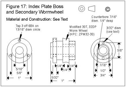
If you are implementing the secondary worm drive, further reduce the diameter to ½" over the last ½" of its length. This forms the shoulder that the secondary worm locates against. Part off to exactly 1" long. Bore out the axial hole of the 32DP, 30T worm wheel to ½" diameter, so that it is a push fit onto the boss. This operation is tricky - the specified worm wheel is made from Delrin, but with careful packing and centering in the 4-jaw, the wheel can be modified without damage to the teeth. Machine a ¾" OD, ½" ID bush ¼" long; I used brass for this, but the material used here is not critical. Assemble the modified worm wheel and then the bush onto the boss with Locktite, clamping them in position to make sure all is square while the Locktite sets.
If the secondary worm drive is not being used, or if it is anticipated that the head will sometimes be used without the secondary worm fitted, the two 3/32" holes can be drilled in the other end of the boss. This can be done using the technique described below for drilling the three holes in the division plate flange, before parting off. A couple of ¾" long 3/32" diameter dowels can then be used to locate the boss in the corresponding holes in the primary worm carrier, preventing the boss from rotating. Of course, you have to remember to remove these dowels before using the secondary worm.
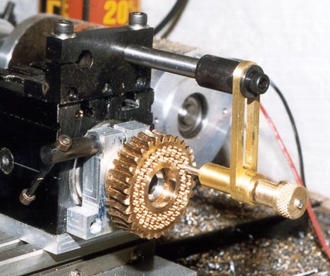
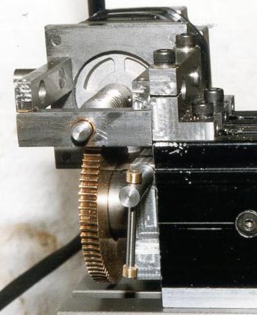
The division plate flange is machined next. This can be achieved by using a short length of 5/32" diameter bar as a stub arbor, Superglued temporarily in place, allowing the boss to be centred in the 4-jaw (or in the 3-jaw if you have an accurate one). Having cut the flange, you can now demonstrate the usefulness of having a dividing head that can use the same accessories as the Taig lathe. Unscrew the chuck, still with the boss in position, and mount it on the nose of the embryonic dividing head. Mount the dividing head on the cross-slide, and position it to drill the three 6BA screw holes, using the Jacobs chuck mounted in the lathe headstock. The worm drive can be operated either with a temporary handle clamped onto the worm shaft, or by means of a screwdriver in the slot of the 2BA screw used for adjusting the end float. The photo below shows a prototype boss being drilled using this set-up, although a different (and less successful, it has to be said!) machining sequence was used for the part shown. Accuracy in positioning these holes is important, as it is necessary for the division plates to be concentric with the boss when they are fitted in position.
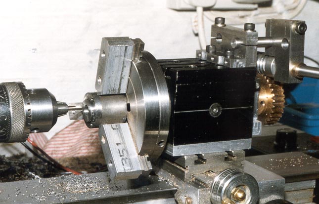
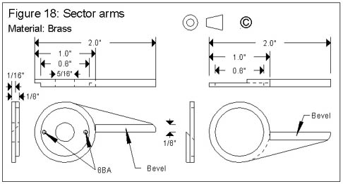
Figure 18 shows these components, which can either be machined from 1/8" thick brass plate or from 1/16" plate components soft soldered together. The construction should be obvious from the drawings; the 1" OD, 0.8" ID portion of the right-hand arm is thinned to 1/16" and fits into the corresponding groove in the left-hand arm. The two 8BA holes are tapped through the thickness of the left-hand arm, and are placed as close as possible to the 0.8" diameter. Two cheese-headed 8BA screws and washers clamp the two components relative to each other, allowing a chosen number of holes in a division plate to be exposed. It may be necessary to thin the left-hand arm underneath these two screw heads, or to apply a slight bend to the washers, in order to achieve the right clamping action. The arms can be used in reverse if necessary for large hole counts. The component sizes are suitable for the chosen division plate diameter of 3"; the dividing head will accommodate larger plates if need be, in which case the sector arms should be lengthened accordingly.
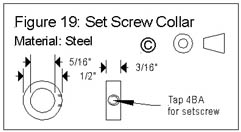
The sector arms, and also the index plate boss, are retained in position by means of a small set screw collar, shown in Figure 19. Making this is a simple turning/boring job; the set screw used is 4BA and 1/8" long, seating in a flat filed in the primary worm shaft. This flat should be deep enough so that the set screw is flush with the surface of the collar when tightened in position. A split spring washer should be placed between the set screw collar and the sector arms and compressed before tightening the set screw; this will provide the necessary friction to ensure that the sector arms remain in the desired position while the indexing arm is rotated.
The construction could have been simplified by combining the set screw collar with the indexing arm clamp; however, the arrangement described allows the indexing arm to be removed and used for direct indexing operations without disturbing the rest of the dividing assembly.
Figure 20 shows the design of the division plates. These are 3" in diameter, as that was the size of a set of brass blanks I had to hand; the head will accommodate larger plates if desired. The central hole size of 5/8" was chosen in order to allow the division plates to fit over the tail of the dividing head spindle to allow their use for direct division, given a suitable mounting arrangement. The options for this kind of use are either to drill and tap the worm wheel to allow it to be used as a division plate boss, or to make up a 1" OD, 5/8" ID set screw collar drilled and tapped for the 6BA mounting screws.
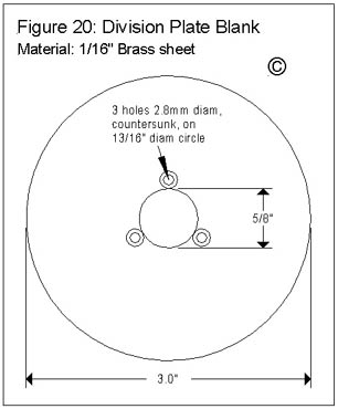
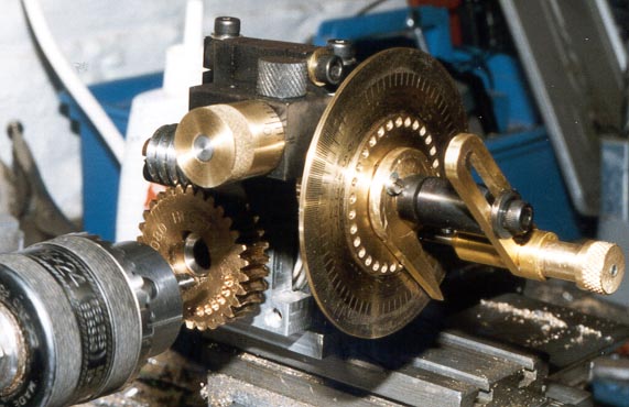
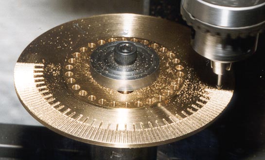
Obviously, a 3" diameter plate is not very useful for direct division when the dividing head is being used on the cross-slide or a milling table without riser blocks, so it may be desirable to cut some smaller diameter plates for this purpose. However, for direct dividing with the lathe headstock, the 3" plates can be useful. It is also worth bearing in mind that the worm wheel itself has useful "real estate" available on it for a couple of low-numbered hole circles; I cut a 30-hole and a 24-hole circle in mine, as can be seen in progress in the next photo. A further option for direct dividing in the lathe is to permanently attach a division plate to the inboard face of the lathe's drive pulley.
The decision as to how many plates to cut, and what numbers of holes to drill in each hole circle, will depend greatly on the applications to which the dividing components will be put. In order to make sensible use of the compound division capability, it is necessary to cut a 30-hole circle; a full rotation of the secondary worm is then equivalent to moving the indexing arm by one hole position. Also, in order to mark the worm thimble with its 40 graduations, a 4-hole circle (or multiple of 4) is needed, as mentioned earlier. Arguably, as compound division will then allow positioning with a theoretical resolution of 1/100th of a degree, it may be that you will never need any further hole circles. However, as compound division involves keeping track of two independent movements, it is likely that users will find it convenient to have a set of hole circles that cover the most-used divisions for their applications. As cutting hole circles can be tedious, the best approach here is to cut the "obvious" circles first – those that allow generation of your most-used divisions, leaving the others until the need arises. A further possibility that can add to the versatility of this device is to mark one division plate as a protractor, with marks at one degree intervals, and longer marks to denote the five and ten degree points. This can be thought of as a simpler alternative to using compound division; in effect, it creates a 360-hole circle, giving 1/30th of a degree of output movement per degree of indexing arm movement. To create such a protractor, a 12-hole (or multiple of 12) circle is needed; this can be easily cut using the 30:1 worm drive, as 2.5 turns of the worm moves the spindle by 1/12th of a revolution. Moving the indexing arm by one hole in the 12-hole circle will rotate the output shaft by 1 degree. It is then straightforward to mount a blank division plate on the business end of the dividing head, mount the dividing head on the cross-slide, and use a sharp scriber mounted in the lathe headstock to mark out the protractor.
Working out whether a given circle of holes can generate the requisite number of divisions is straightforward. Multiply the number of holes in the circle by the worm drive ratio; if you can divide the result by the desired number of divisions with no remainder, then the chosen circle can be used successfully. For example, the four hole circle will allow the dividing head to generate 40 divisions, as 4 X 30 gives 120, and 120/40 is 3 with no remainder. This also tells you that the indexing arm moves 3 holes between each division. The same principle applies when using direct division, except the drive ratio is 1:1 instead of 30:1.
The hole circles are easily cut using a 3/32" diameter drill – the most convenient approach here is to use a No. centre drill, which has this diameter of pilot drill. This pilot drill is also long enough to drill through a 3/32" plate. Using this size of hole, it is possible to fit an 80-hole circle onto the periphery of a 3" division plate. Leaving about 1/8" between circles, with care it is possible to squeeze up to 8 circles onto each plate; the smallest circle will be limited to a maximum of around 30 holes. It is worth remembering to mark the plate with the number of holes in each circle; counting holes several months later when you have forgotten what you did is a very tedious experience!
As mentioned above, compound division requires a minimum of two circles, one with 30 holes and one with 4 holes; the latter in order to be able to mark out the graduations on the thimble. If you plan to cut a protractor, a 12-hole circle would usefully pass as a substitute for the 4-hole circle. It is useful to make up a mounting arbor to help with division plate drilling; this needs to have the right size of shoulder for the plates to mount on, the remainder being machined to suit your preferred method of work holding. The simplest approach is to machine a division plate arbor from one of the blank arbors that can be obtained for the Taig lathe. These arbors are basically a short length of 1" diameter steel stock with a female thread at one end that fits the ¾" nose thread of the lathe spindle, and a 1" diameter washer held in place with a UNC 8-32 cap screw at the other. A 5/8" shoulder can be machined on the blank end of the arbor; the washer and cap screw will then hold the plate firm for drilling. The arbor is then transferred to the dividing head for the plate drilling operations. Once the two initial hole circles have been cut in the first plate, the compound indexing components (and/or the protractor) can be completed, and then the dividing head can be used to cut any other size of hole circle that may be needed.
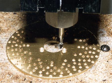
Of course, if you have a CNC mill to hand, cutting division plates is a trivial exercise; my plates were all cut using the Taig CNC mill, as was the protractor. The next photo shows a plate being machined; I attached it to a backing board, and then drilled the hole circles, using a centre drill, under CNC control. Next, the central countersunk holes were drilled, then the central 5/8" hole milled out using a 1/8" end mill.
The next photo shows the protractor engraving in progress; the graduations have been added to a plate that has a single 30-hole circle, and the mill is now adding the numbering to mark each 10 degree interval.
As with the graduated thimble, the approach of filling the engraved marks with black felt tip greatly enhances the readability of the scale. The engraving cutter I used for these parts is one sold for the Dremel hand tools, with a small conical cutting tip; simple cutters can also be made by grinding a V-tip onto a broken centre drill. Since then, I have acquired a proper carbide engraving bit, ground to the right relief angles, which should improve the quality of my engraving.
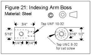
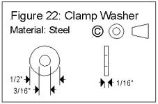
Figure 21 shows the Indexing Arm Boss - a ¾" length of ½" diameter steel, bored 5/16" at one end and tapped 10-32 UNF at the other, and fitted with an 8-32 UNC set screw. A ½" diameter washer is also needed, shown in Figure 22. The boss fits onto the end of the primary worm shaft, located by the 8-32 set screw. A 10-32 cap screw is used, with the washer, to clamp the indexing arm in position.
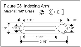
The indexing arm itself is shown in Figure 23, cut from 1/8" thick brass plate. The 3/8" diameter hole takes the detent assembly; the longitudinal slot allows adjustment of the detent position relative to the division plate.
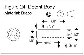
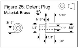
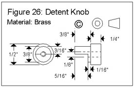
The body of the detent assembly is shown in Figure 24. This is soft soldered into the 3/8" diameter hole in the indexing arm, ensuring that it ends up perpendicular to the arm. The detent plug (Figure 25) and the detent knob (Figure 26) are designed to allow the detent pin (Figure 27) to be locked in the raised position. When moving the detent from one division plate hole to the next, you pull back the knob and rotate it half a turn to lock; another half turn allows the pin to be dropped into the next hole. A short spring will be needed to complete this assembly; it needs to be about ½" long, with an ID greater than 1/8" and an OD less than ¼". In operation, this spring will be required to compress by 5/16". The one I used happened to be on hand in my junk box; a suitable spring could be wound from piano wire if necessary.
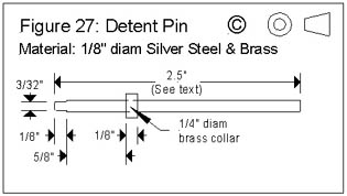
The detent pin was made from a length of 1/8" silver steel rod. The last 1/8" is reduced to 3/32" diameter to match the size of holes drilled in the division plates; the diagram shows this as parallel turned, but a taper could be turned if preferred. The brass collar is soft soldered (or Locktited) in place ¾" from the tip of the pin. This component should not be cut to final length until the other detent components are complete and ready to assemble. A trial assembly will indicate the exact pin length required - fit the pin into the body, followed by the spring, the plug and the knob, the latter fitted in the lowered position. Mark the pin for cutting so that its end will be flush with the top of the knob. Final assembly can then be achieved by using a drop of Locktite to fix the plug into the body and a second drop to attach the knob to the pin.
The final length of the primary worm shaft can now be determined. With the indexing arm boss in place on the end of the over-length shaft, attach the indexing arm and detent assembly and measure the distance between the shoulder on the point of the detent pin and the surface of the division plate. This tells you by how much the shaft should be shortened. Once the shaft is cut to length, file a flat to act as a pad for the set screw. I found that filing the last ¾" of the shaft flat formed a suitable pad both for this screw and for the set screw collar.
Tailstock Support
For some operations, particularly when working on long items, it will be necessary to support the free end of the work piece using a tailstock of some kind. Clearly, if the dividing components are being used with the Taig lathe headstock, it may be sufficient to press the Taig tailstock into service for this purpose. However, particularly when using the dividing head in the mill, it will sometimes be necessary to have a separate tailstock that can be clamped to the milling table.
Figures 28, 29 and 30 show the components of a simple tailstock that can be used with the dividing head. The intent is that it should be used with the axis of the dividing head aligned with the X-axis of the milling table, and it assumes that the T-slots are on 1" centres also aligned with the X-axis, as is the case with the Taig mill.
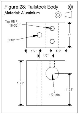
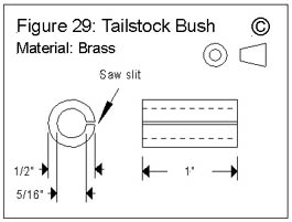
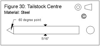
The body of the tailstock, Figure 28, is a block of aluminium with a 3/16" vertical through hole for a UNF 10-32 T-bolt, two tapped vertical holes for 10-32 pinch bolts, and an axial through hole ½" diameter. The ½" diameter hole is nominally 1.25" from the base of the block; however, this should be adjusted to match the centre height of the dividing head. The ½" diameter hole and the T-bolt hole are offset ½" relative to each other, to bring the ½" hole onto the same axis as the dividing head spindle when both items are mounted on the milling table. Figure 29 shows a 5/16" ID split bush that fits into the ½" hole, and Figure 30 shows a plain centre cut from 5/16" steel. The split bush and clamping screws allow the centre position to be adjusted. The length of the tailstock centre can be chosen to suit the application. Similarly, if a sturdier centre is needed, dispense with the split bush and cut a ½" diameter centre.
Conveniently, this tailstock design also doubles very nicely as a boring tool holder for use in the Taig lathe - in fact, the design is simply a slight modification of a boring bar holder that I made some while ago, before embarking on the dividing head design. The Sumitomo boring bar mentioned earlier fits the 5/16" ID bush, and further bushes can be made to suit other bar diameters. The next photo shows the tailstock in use as a boring bar holder, fitted with a slightly larger boring bar with a Sandvik carbide insert.
This completes the constructional details. The remaining paragraphs describe how the components can be combined to provide the different indexing functions. The photos used show the division components used with the dividing head spindle, but all setups illustrated can just as easily be achieved with the division components attached to the lathe itself.
The set-up for direct dividing can be seen in the next photo.
The support bracket is bolted in place on top of the spindle, and a length of 5/16" steel bar is used as a support for the detent. The complete indexing arm assembly, including the boss, is used as the detent; the adjustable clamp on the support bracket allows the detent pin to be aligned with the selected hole circle - in this case, one of the circles I drilled in the 30T worm wheel. Using this arrangement, it is highly advisable to make use of the spindle brake to lock the spindle between operations.
The next two photos show the dividing head fitted for compound division, configured for use on the lathe cross-slide with the spindle pointing to the left.
Reversing the "handedness" is achieved as follows. Remove the dividing assembly from the support bracket, and reverse the fitting of the brake pinch bolt assembly. Remove the secondary worm assembly by loosening its pinch bolt, flip it over and refit it from the other side; unscrew the thumbscrew and refit it in the other end of the worm lock. Loosen the pinch bolt holding the 5/16" support bar into the primary worm carrier, and slide it through so that it now protrudes from the other side; re-tighten the pinch bolt. The dividing assembly can now be refitted to the support bracket, using the other of the two split clamps.
For simple division, ignore the secondary worm; lock it in position using the thumb screw, or remove it and fit the pins to lock the indexing plate boss in position. Select the desired hole circle, adjusting the indexing arm clamp to line up the indexing pin correctly. Calculate how many complete revolutions, plus how many holes in the circle, are needed between each division, and adjust the sector arms to expose the requisite number of holes in the circle. This calculation goes as follows:
Compound Division
The dividing attachment is assembled with the secondary worm drive in place, and a plate with a 30-hole circle fitted to the indexing plate boss. With this arrangement, the dividing attachment becomes a means of positioning the output spindle in increments of 1/100th of a degree, corresponding to a single division on the graduated thimble. Hence, a full rotation of the graduated thimble (40 divisions) gives 0.4 degrees of spindle rotation; this is exactly the same as moving the indexing arm by one hole in the 30-hole circle. A full rotation of the indexing arm gives 12 degrees on the spindle; 30 rotations of the indexing arm gives a full 360 degrees. In order to index between divisions, it is likely to be necessary to move both the indexing arm and the thimble. To calculate the necessary movements, divide 360 by the number of divisions required giving a (probably fractional) number of degrees per division. This can then be converted into the number of full turns of the indexing arm plus the number of holes in the 30-hole circle, plus the number of divisions on the thimble. For example, creating 16 equal divisions requires 22.5 degrees per division. This is equivalent to one full rotation of the indexing arm (12 degrees), plus 26 holes in the 30-hole circle (10.4 degrees) plus 10 divisions on the thimble (0.1 degrees), giving a total of 22.5.
Where the calculation does not result in an integral number of 1/100ths of a degree per division, an allowance needs to be made for the error in calculating the movements per division by adding in an extra 1/100th of a degree every so often, so that the error is evenly spread out among the divisions rather than being "concentrated" in the last division. To give a very simple example, if you wanted to produce 320 divisions, then it would be necessary to rotate the spindle by 1.125 degrees per division. This is equivalent to 2 holes in the 30-hole circle, plus 32 divisions on the thimble, giving 1.12 degrees. However, this is .005 of a degree too little; on all but the last division, this would not be noticeable, but the error in the size of the last division would be 320 times the individual error, or 1.6 degrees. The last division would end up more than twice the desired width. The solution is to use 32/100ths on the thimble for the first, third, fifth,..., and 319th division, and use 33/100ths for the even numbered divisions.
Keeping track of the next setting of the thimble can be tricky, especially if the number is changing from division to division. The safest approach is to calculate it all out beforehand, and to make up a table detailing where you expect to move the indexing arm and thimble to create each division. The alternative is to work it out in your head - and run the risk of messing up your evening's work.
For many purposes, a protractor can be used as a simpler alternative to compound division. The protractor can be viewed as a 360-hole circle, or as a means of positioning the output spindle to a resolution of 1/30ths of a degree. Either way, the calculations involved are similar to those described above; again, it is well worth writing out a table of protractor positions for each division in order to avoid turning your hard work into scrap by careless application of mental arithmetic!
The next photo shows how the stepper motor assembly is attached to the dividing head.
For most purposes, the motor will only be used with one "handedness", as the CNC control software will make an assumption as to which way the motor (and hence, the spindle) will rotate for positive and negative movements of that axis. If your control software and hardware is capable of driving 4 axes simultaneously, then you can choose the physical orientation that you prefer, and then define the appropriate direction of rotation by means of software configuration parameters. If, as in the example I gave earlier of graduating the thimble, you "borrow" the X or Y axis control signals to drive the 4th axis motor, you probably don't want to change software settings each time you switch between linear and rotary axes, so you will be stuck with fitting the motor in one orientation only, and will have to experiment to work out what that orientation should be. However, the ability to rapidly change the "handedness" of the dividing head by reversing the motor mounting position makes for some amusing possibilities; for example, you could produce left-handed and right-handed versions of a component from the same CNC control program just by reversing the orientation of the motor.
Milling a 3/8"/24TPI thread, using a solid carbide V-tipped engraving cutter (supplied by Pantograph Services in Leeds, UK). This photo shows the first few revs of the first pass. The end result is a drill chuck arbor for use in the Taig lathe or mill, cut from one of Taig's "blank arbors". The cutter is 1/4" diameter, 60 degree tip, 15 thou cutting width at the tip. I had to use a 3/8"/24 die for the last couple of turns, as the width of the cutter prevents getting closer than a hair over 1/8" from the shoulder. Demonstrates that the principle works, and similar 1/8" cutters can be had that would allow a closer approach to the shoulder.
Cutting the centre wheel for John Wilding's 3/4-second pendulum clock (serialised in Model Engineer). This is a worm wheel, driven by a 12 TPI worm. The fly cutter is a modified carbide-tipped threading tool. See also the article describing engraving a chapter ring for this clock, for further examples of the use of this dividing head.
Ref 1 Peatol Machine Tools, 19 Knightlow Road, Harborne, Birmingham B17 89S, UK.
Tel/Fax: 0121 429 1015
Ref 2 Taig Tools, 12419 E. Nightingale Lane, Chandler, Arizona 85249, USA. Tel: (602) 895-6978
Website: http://www.taigtools.com/
Quantum CNC is the European distributor of the CNC version of the Taig desktop mill; they also supply some interesting CAD/CAM software products.
Ref 3 HPC Gears, Foxwood Industrial Park, Chesterfield, S41 9RN, UK.
Tel: 01246 260003 Fax: 01246 260003
Website: http://www.hpcgears.com/
Ref 4 Sumitomo inserts and tools can be obtained from Penco, 3, Greenfield Close, Sheffield, S8 7RP, UK.
Tel/Fax 0114 237 7716
Ref 5 10-32 UNF screws can be obtained from Emkay Supplies, 74 Pepys Way, Rochester, Kent, ME2 3LL. Tel: 01634 717256
Ref 6 Nema 23 stepper motors can be obtained from Model Motors Direct, Keepers Cottage, Home Farm, Iwerne Minster, Dorset, DT11 8LB. Tel: 01747 812440.
Ref 7 Engraving equipment and cutters can be obtained from Pantograph Services, Unit 8, Felnex Close, Cross Green, Leeds, LS9 0SR, UK.
Tel: 0113 249 6161. Fax: 0113 249 7033.
Ref 8 Sandvik carbide inserts supplied by Greenwood Tools, Sherwood House, Sherwood Road, Bromsgrove, Worcs. B60 3DR, UK.
Tel: 01527 877576. Fax: 01527 579365.
A Comprehensive Dividing Capability for the Taig (Peatol) Lathe and Mill
© Tony Jeffree 2000
All Rights Reserved
Email me at this address...
website ({at}) jeffree.co.uk
Return to Model Engineering Activities page...