Introduction
This wheel cutting engine design was a result of a need to be able to demonstrate the DivisionMaster controller in a realistic, practical model engineering application, back in the days when I was actively selling the controller at Model Engineering exhibitions (nowadays it is available only through the Model Engineers Digital Workshop).
For those that didn't read Alan Timmins' review of the controller in MEW Issue 92, DivisionMaster is a hand-held controller that allows you to control the movement of a rotary axis (a rotary table, dividing head, - etc.) automatically, by replacing the manual handwheel on the rotary device with a stepper motor. Once set up for the appropriate number of divisions (or degrees), a single keystroke causes the controller to advance the rotary axis to the next incremental position. Now, that sounds all very well in theory, but it may not immediately catch the imagination, or translate into real ideas of what the controller might be used for, in the way that a real live demonstration would do. Hence, I was keen to put together a demonstration that would be rather more interesting to watch than a rotary table or dividing head going round, and that would give a clearer picture of what the controller is capable of doing in a real application.
Dick Stephen suggested to me that the obvious thing to do would be to demonstrate cutting a clock wheel. As I have a Peatol lathe, it didn't sound too onerous to set up a wheel cutting demonstration using that as a base. Even better, I realised that I had some spare bits & pieces lying around that could be pressed into service to build a dedicated wheel cutting engine, including a length of aluminium extrusion of the same profile as the Peatol lathe bed, fitted with a rather beaten-up spare Peatol saddle and cross-slide. I also had a spare Peatol headstock and a spare capacitor start AC motor to hand. All in all, this seemed like a good basis to start from.
Overall "design"
The final machine setup owes more to "Scrapheap Challenge" than to showroom-quality engineering, so describing it as having a design may be over-egging it somewhat, but there were nonetheless one or two elements of design involved in putting it all together. Pay close attention to the following description, or you may well miss them!
Given that the primary purpose was to be able to give a demonstration of wheelcutting, it was important to end up with something that could be operated from one side of a table, and that could simultaneously be viewed in operation from the other side, without motors and other bits and pieces obscuring the view. This constraint resulted in adopting the layout shown in Photo 1; the "lathe bed" extrusion runs (conventionally) left-to-right, and the spare Peatol lathe headstock (that was pressed into service as the cutter spindle) was mounted with its axis at right-angles to the bed, spindle nose pointing away from the operator. This allowed the motor to be mounted to the far left of the baseboard, well out of the way and not obscuring the view of the "business end" of the machine that would be clearly visible from the side furthest from the operator.
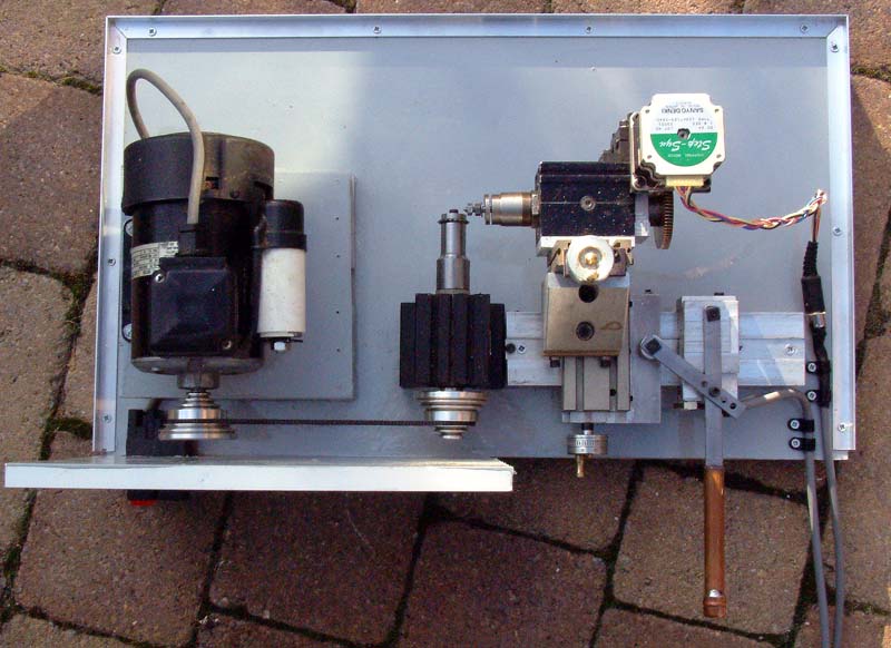
Photo 1 - overall layout
To make a successful wheel-cutting engine, you need to be able to mount the dividing head in such a way that it can move in three axes:
- To adjust the distance between the dividing head axis and the axis of the cutter spindle - i.e., to adjust the depth of cut and to accommodate different sizes of wheel;
- To adjust the axis of the dividing head to be in line with the plane of the cutter, to ensure that the gear teeth are properly radial, or to deliberately make non-radial cuts (for example, when using a slitting saw to cut a ratchet tooth);
- To allow the wheel blank to be passed across the cutter.
The right-left (X-direction) saddle traverse along the "lathe bed" extrusion would give me the movement of the blank across the cutter, and the saddle's cross-slide movement (Y-direction) would allow the dividing head spindle to be aligned (or deliberately misaligned) with the plane of the cutter. The third movement (Z-direction), to adjust depth of cut, would be achieved by mounting the dividing head on the Peatol vertical "milling" slide, and in turn attaching the milling slide to the saddle's cross-slide. The mounting arrangements can be seen in more detail in Photos 1 through 3.
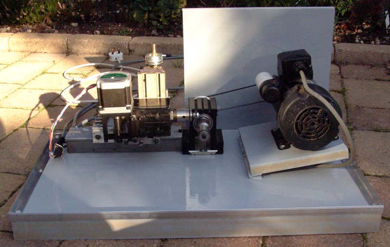
Photo 2 - front view
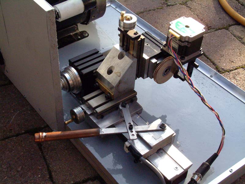
Photo 3 - lever operation detail
The dividing head that I used is based on a modified Peatol milling spindle, and is the prototype of the dividing head design that can be seen here (originally published in issues 62 and 63 of MEW). However, the basic idea behind the dividing head is a simple one - attach a worm wheel to the back of the spindle, attach a worm to a stepper motor, and mount the motor/worm such that it engages the worm wheel and can be adjusted to remove backlash.
The saddle traverse (X-direction) is controlled by a lever arm arrangement (see Photo 4), with a cap head screw acting as a saddle stop at the left hand side, and an adjustable stop at the right hand side made from a section of Peatol lathe raising block. This latter stop also doubles as a mount for one end of the lever linkage, the other end of the linkage being attached to the saddle itself via a simple pillar support.
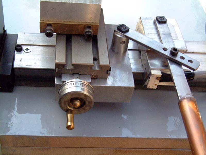
Photo 4 - Saddle traverse detail
One of the "features" of the DivisionMaster controller is that it can use an external trigger to advance the rotary axis to the next division, and this feature is utilized by wiring a small "normally open" microswitch to the relevant interface pins on the controller. This microswitch can be seen in Photo 4, mounted on the right hand saddle stop just to the left of the operating lever, so that when the saddle hits the stop, the microswitch contacts close, and the controller drives the dividing head automatically to the next division. So, when set up for the right depth of cut and the right number of teeth, cutting a complete wheel becomes a simple task of cranking the lever arm back and forth once for each tooth-space.
Construction
There is not a great deal to be said about the construction, and I don't plan to include detailed drawings, as most of the constructional details can be seen from the photos anyway, and in all likelihood, anyone building a similar machine would start from a different set of "scrapheap" components, which will inevitably cause a re-think of the design, particularly with regard to relative positions of things.
In keeping with the need to make something reasonably portable, I used two thicknesses of 19mm MDF as the baseboard, glued together with wood glue. The overall dimensions of the baseboard started off at about 2 feet long by 16 inches wide, but the final layout didn't take as much space as I expected, so the width was reduced to 14". Clearly, this is not a particularly rigid material, but it is plenty rigid enough for this application, and has the great advantage that (re-)positioning of components is easily achieved with wood screws, and machining involves only woodworking tools.
The motor was mounted on a hinged board approx 7" square, again cut from MDF, positioned such that the weight of the motor tensions the belt, and with the hinges on the right-hand edge as viewed by the operator. The drive belt and pulleys are standard Peatol items. The motor should be mounted first; then the cutter spindle can be placed in a position such that when the belt is fitted it will be properly tensioned. If you use a motor that is overweight, it would be smart to limit the belt tension by fitting an adjustable stop under the hinge plate at the left hand side; however, with the motor I used this was not an issue.
The headstock that is used for the cutter spindle came with its own short length of "lathe bed" extrusion to be used as a mounting plate, pre-drilled with two mounting holes. This mounting plate was simply screwed directly to the base with wood screws. The headstock clamping bolts allow the headstock position to be adjusted if necessary, to ensure proper alignment of the driving and driven pulleys.
The 9" long section of "lathe bed" was mounted on top of a 9" length of square section, thin walled steel tube bought from B&Q, 40mm by 27mm. The lathe bed was first stuck onto the wide side of the tube with Araldite, having first de-greased and roughened both components. Six mounting holes were then drilled vertically through both components along the centre line of the bed, allowing the bed assembly to be screwed to the base with wood screws. The bed is positioned so that the edge nearest the operator lines up with the back end of the headstock's "legs". The square section tube raises the bed off the baseboard enough o allow the saddle to slide to & fro freely, while also adding a bit of stiffness to the aluminium extrusion.
The operating lever consists of a strip of 1/8" by ½" steel, 8" long, pivoted at one end, and with a second pivot hole 2.5" from that end (actually 2.25" between pivot centres). The end is pivoted on the right-hand saddle stop using a simple stud and nut. A second strip of steel 3.5" long links from the second hole in the operating lever to a mounting post that is screwed onto the right hand side of the saddle. I drilled four holes approx ¼" apart at one end of this second lever, to allow its effective length to be adjusted according to the amount of travel needed. The pivot on the top of the mounting post is another stud and nut affair, and the pivot between the two arms is a simple nut and bolt. The mounting post is a piece of aluminium bar cut to the right length (3/4" or so) such that the operating lever ends up horizontal.
The right-hand saddle stop is made from a Peatol riser block; I had long ago cut one of my riser blocks in two, realising that the tailstock didn't need the whole length of the standard Peatol riser block, and had used the smaller piece to build a filing rest. The larger piece was pressed into service for this project; unscrewing the stud for the operating lever quickly converts it back to its former use. The microswitch I used was a type that has a spring steel operating lever. This was screwed to the operator's side of the saddle stop, using a single screw tapped into the saddle stop block, and allowing the switch to be rotated to adjust its position so that the switch is tripped when the saddle is hard against the stop. At the left hand end of the bed extrusion, a cap head screw (visible in Photo 4) threaded into the bed extrusion acts as a stop to limit the movement of the saddle.
To make the operating lever rather more comfortable to use, I sleeved the end with a length of 15mm copper plumbing pipe, capped with a standard 15mm capillary end stop fitting. This was held in place by the simple expedient of filling the tube with hot-melt glue, heating up the operating lever, sliding the tube over the end of the lever, and then cleaning off the residual glue from the joint. The complete handle and operating linkage can be seen in Photo 3.
In order to make the whole assembly safe for public demonstration purposes, I constructed a cover from polystyrene sheet and aluminium angle, both purchased from B&Q; this can be seen in position in Photo 5.
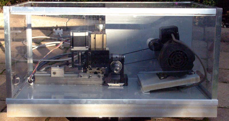
Photo 5 - plastic/metal framed cover in place
The parts were cut to size/length, mitred where appropriate, and assembled using rapid curing epoxy resin adhesives. A useful tip I discovered in this process was that uncured and semi-cured epoxy can be removed from fingers and from assembled components with a rag soaked in a commercial paintbrush cleaning fluid; however, I would advise testing out your particular cleaner on a sample of the plastic sheet before doing anything irrevocable.
The cutter arbor and the wheel blank arbor are both machined from Peatol "Blank Arbors"; these are lengths of 1" diam free machining steel, bored and threaded for the 3/14-16TPI spindle nose, and can be seen in Photo 6. The cutter arbor was machined down to be a close fit to the bore of the gear cutter, and a simple clamping disc and cap head screw holds it in position. The wheel blank arbor was turned down to 3/16" diameter over a length of an inch or thereabouts, and threaded to take a UNF 10-32 nut. These arbors should either be cross-drilled or have spanner flats machined on them to facilitate easy tightening/removal from the cutter spindle or the dividing head.
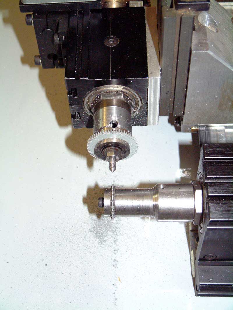
Photo 6 - Cutting teeth
Closing words
Photo 6 shows the end result of cutting a gear wheel, using a .55 mod multi-tooth gear cutter. The blank used in the setup here was a disc of aluminium cut out from the base of a DivisionMaster controller case - the hole for the cooling fan being 40mm diameter, the "scrap" disc was a good size for this demonstration, and was about right for a wheel of 60 teeth using a 0.55 module cutter. A light spray with WD 40 made for a clean cut; this cast aluminium material in any case tends to cut fairly crisply, unlike the more sticky forms of aluminium that is often found in commercial bar/sheet stock. Photo 7 shows a view of the final setup, with the controller to the left hand side of the wheelcutting engine. The photo shows the connections to the controller; the left-hand cable is the motor connection, the middle cable carries the connections to the microswitch, and the right-hand cable is the controller's power supply.
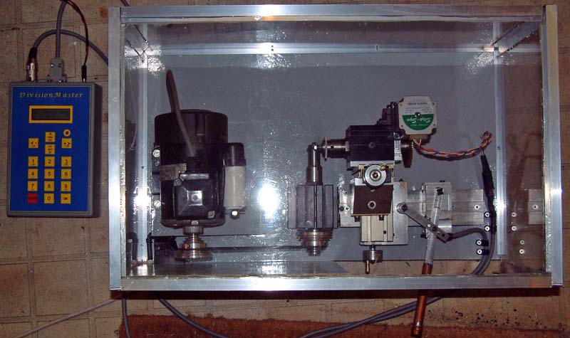
Photo 7 - complete with Divisionmaster controller
For clock wheel cutting, the setup seems to work pretty well, and would probably cope fine with cutting pinions in brass. Obviously, if heavier work was contemplated, such as gear or pinion cutting in steel, then a more robust setup would probably be appropriate.
An obvious substitution for the aluminium extrusion used for the X-axis would be to use a proper Peatol lathe bed, as this comes with an integral support tube and mounting foot; this would give an X travel significantly longer than is strictly necessary, but might be a good option for existing Taig owners that fancy treating themselves to a new lathe and pressing the older bed into service for wheel cutting. At one point in this project, I was eyeing up a cheap Eastern-origin cross-vice that is languishing in a corner of my workshop, and that would have served as an alternative for supplying the X and Y movements; there are also a wide variety of inexpensive X-Y tables, available from the usual suspects, that could be pressed into service very easily.
A CNC Wheel Cutting Engine