Introduction
In part 1, I described modifications to the ML-7 leadscrew thrust bearings and the installation of a stepper motor to drive the Myford leadscrew. In this second article, I will describe modifications to the cross slide to install a stepper motor to drive the cross slide feed screw. As I said in Part 1, the intent with this particular conversion was to make it possible to retain the option of manual operation of the lathe so that, for simple jobs, the lathe can be used without the need to use the CNC control, and also so that the lathe can be returned to original specification very easily if the owner decides that is desirable for any reason. The one casualty in this part of the conversion was the graduated dial on the cross slide, which I modified from its original form. However, this is not an expensive item to purchase as a spare from Myford, so having to buy an extra dial to restore the lathe to its original condition didn't seem like too much of a compromise. Alternatively, as the dial is basically just a slice of steel bar, marked with 100 graduations and having a ¼" axial threaded hole, making this part for the purposes of the conversion wouldn't be terribly hard if so desired.
Design decisions
As with the leadscrew conversion in Part 1, it is desirable to properly control end float in the cross-slide feed screw, and also to reduce the frictional load seen by the motor when driving it. In order to achieve this, I used the cross-slide bearing conversion kit sold by Arc Eurotrade. This consists of a pair of roller thrust bearings, part number NTA411, and a tiny ball race, part number R168, mounted in a bearing housing machined from 3/8" aluminium plate. This particular conversion turns out to be extremely worthwhile even for a manual lathe; the difference in the cross-slide operation is enormous. Adjusting the bearing for zero end float is very simple, and the reduction in bearing friction vastly improves the "feel" of the cross slide feed.
In order to provide a support for the stepper motor drive to the cross slide, the conversion involves a bearing and motor mount bracket that replaces the standard Myford component; the bracket allows the stepper motor to be mounted below the feed-screw and for drive to be achieved using a toothed "timing" belt and a pair of pulleys, and retains the ability to use the conventional ball handle to operate the screw. The top slide is still available for full manual operation in this conversion; alternatively, the top slide could be removed and the tool-post mounted on a raising block to restore the correct tool height - the advantage of going this route is that the setup will be somewhat stiffer.
As with the leadscrew conversion, I used a NEMA 23 frame stepper to drive the cross-slide feedscrew. However, in this case I chose a smaller motor - an Astrosyn 140 oz-in motor (part number MY 2801-05, the same motors that I used in my Taig lathe CNC conversion - MEW issues 120 and 121). I used a 2:1 reduction drive between motor and the cross-slide feedscrew, again using "timing belt" pulleys supplied by RS Components, but 2.5mm pitch, 6mm wide in this case. The cross-slide requires significantly less torque to drive than the main leadscrew - partly because the frictional and inertial load seen by the motor is smaller, and partly because most of the cutting load will be on the leadscrew. In fact, just to see how small a motor it is possible to use, I tried using a NEMA 17 frame motor, rated at 36 Ncm torque (Arc Eurotrade part number 160-010-00100) with this setup, and found that it was capable of making surprisingly heavy cuts. However, for more reliable use, it is as well to have a bit more headroom than these small motors give you.
Constructional details
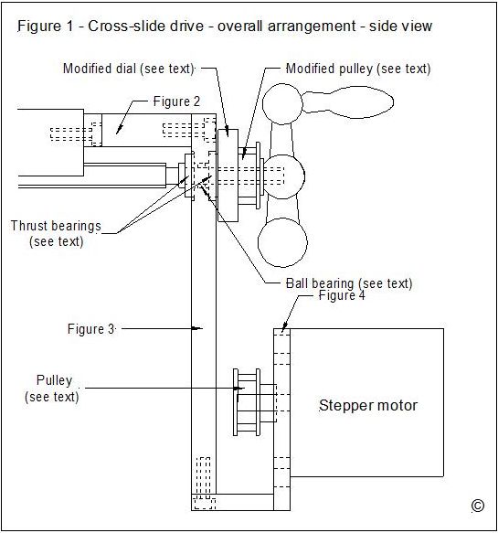
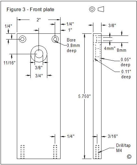
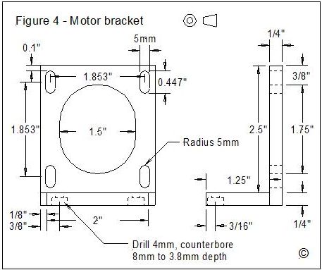
The overall arrangement of the combined motor mount and bearing housing can be seen in Figure 1; all of the components were fabricated from aluminium stock, but steel would be suitable also. The original Myford bearing plate is replaced by the top plate (Figure 2); the front plate (Figure 3) attaches to the top plate with a pair of M4 cap head screws, and has pockets machined on either side to act as housings for the thrust bearings, and a through bore to carry the central ball race. The motor bracket is made from ¼" aluminium angle, and attaches to the base of the front plate (Figure 4).
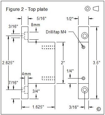
Machining of the top plate is pretty self-explanatory from the detail in Figure 2; I used a length of 2" X ½" bar stock as the starting point. Photo 1 shows machining in progress for one of the mounting lugs. The only comment needed here is that the counterbored holes that take the original Myford 3/16" cap head screws are intentionally placed 1/16" below the centre line so that the top surface of the top plate ends up pretty much where the original Myford bracket did. As all of the other critical dimensions, such as placing of the bearings and the motor, are referenced from the locations of these holes, it is important to maintain accuracy here.
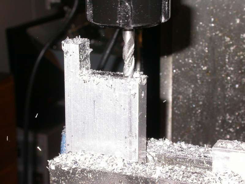
Photo 1: Machining the top plate
The front plate (Figure 3) is also fairly straightforward, and was machined from 2" X 3/8" aluminium bar. The deeper bearing recess is on the face of the plate that faces the lathe operator; the depth of this is critical to ensure that the graduated dial will act as a bearing cover for the front thrust race and still have a couple of thou of running clearance between it and the front plate. The rear recess is less critical, and could in fact be bored a little deeper in order to give more protection to the rear thrust race. If you were feeling energetic, it wouldn't be hard to add a bearing cover for the rear bearing if so desired.
The motor bracket (Figure 4) started life as a 2.25" length of 3" X 3" X 1/4" aluminium angle. The vertical arm stays as 2.25" wide; the shorter horizontal arm is tapered to 2" wide to match the width of the front plate. Apart from that, there is nothing terribly complicated about its construction; in my case, I was able to use my CNC-converted X3 mill to make short work of machining out the various holes and cutting the taper; the final stages of machining can be seen in Photo 2.
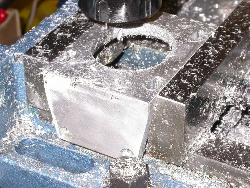
Photo 2: Machining the motor bracket
The other items that need to be machined are the two pulleys and the graduated dial. The smaller (14 tooth) pulley simply needs to be bored out to accept the ¼" diameter motor shaft, and the plain boss is drilled and tapped for a suitable set screw (I happened to have a 4BA screw to hand; the size is not critical).
The larger (28 tooth) pulley is a little more complex. First, it is mounted in the lathe chuck, held by the plain boss; if like me you have a 3-jaw that will hold concentricity, then use that; otherwise, hold it in the 4-jaw and dial it in for concentricity. The bore is then drilled and tapped ¼" BSF to match the threads on the end of the cross-slide feed screw. Next, the last millimetre or so is machined off so that the flange is completely removed, but the toothed part of the pulley is not reduced in length at all - see Photo 3. Finally, the pulley is reversed in the chuck, using suitable protective pads to avoid the teeth being bruised at all (I used a strip of thin aluminium sheet wrapped around the pulley), and the plain boss is shortened so that the overall length of the pulley after machining is 11mm (see Photo 4). Finally, file a pair of flats on the plain boss to aid with tightening later on.
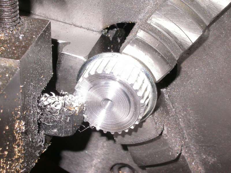
Photo 3: Pulley modification
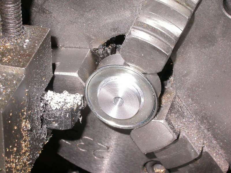
Photo 4: Shortening the pulley boss
The graduated dial is the final component to modify. As you need the cross slide to be operable in order to do this, what I did was to borrow the dial from the top slide and modified that one. The dials on my lathe are the more modern cylindrical ones; if your lathe has the older tapering dials, you will need to obtain one of the new ones to modify, or you could make your own of course. The modification is simply to machine off the boss with the flats, as shown in Photo 5, and reduces the length of the dial to approximately 8mm, so the numbers just remain intact. The combined length of the dial and the pulley should be a little more than the original dial, and the machined face of the dial will double as a retaining flange for the belt, as seen in Photo 6.
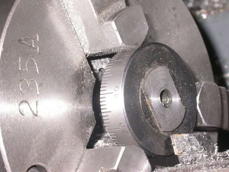
Photo 5: Modifying the graduated dial
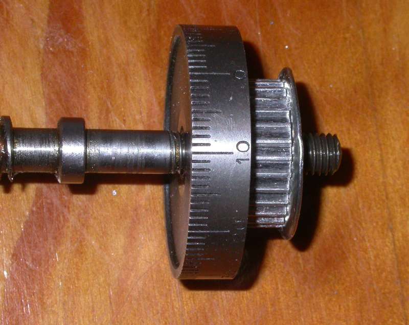
Photo 6: The combined dial/pulley
Assembly
The new bearings and mounting arrangements can now be assembled. First, remove the cross-slide crank handle and graduated dial, and remove the bearing bracket. The top bracket is then fitted in place of the original bearing bracket using the original cap screws, noting that the bracket must be mounted the right way up as discussed earlier.
Next, fit one of the thrust bearings to the end of the feed screw, and fit the small ball race to the bore in the front plate. Note that this should be a slip fit in the bore; as the bearing is so small, there would be a significant risk of distorting the bearing if the fit is too tight. The front plate can now be fitted over the end of the leadscrew and screwed to the top plate with a pair of M4 cap head screws. I filed a notch at the top of the front plate to act as a witness mark for the graduated dial, as can be seen in Photo 7. The second thrust bearing is then fitted to the front housing. The modified graduated dial can be threaded onto the feedscrew; I used a small drop of Locktite threadlocker on the screw, taking care not to contaminate the thrust bearings. The dial should be adjusted so that there is absolutely no play in the bearings but not so tight that the bearings tighten up or run rough. The pulley is then threaded on to lock against the dial, again using threadlocker. Finally, yet more threadlocker, and the crank handle is tightened in place.
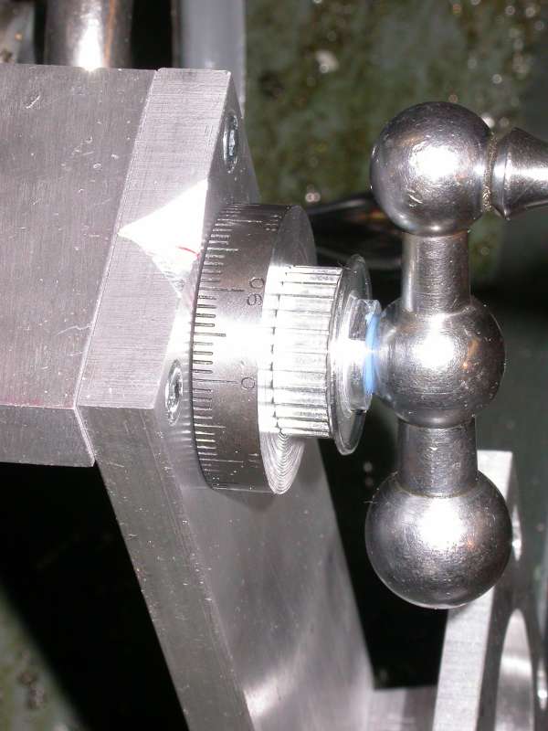
Photo 7: Assembly in progress
The motor bracket is then added to the bottom of the front plate, held in place with two more M4 cap screws. File a flat on the motor shaft, and mount the small pulley on the shaft with the pulley boss towards the motor; the motor can then be offered up to the mounting bracket to check the alignment of the pulleys. The simplest way to do this is to fit the drive belt and crank the handle to see where the belt rides on the bottom pulley; slide the pulley on the shaft so that the belt will tend to ride in the centre of both pulleys, and tighten the set screw once the right position is found. The motor can then be fitted permanently using M5 cap screws and Nylock locknuts; slide the motor down in the mounting slots to tighten the belt appropriately. The completed assembly can be seen in Photos 8 and 9.
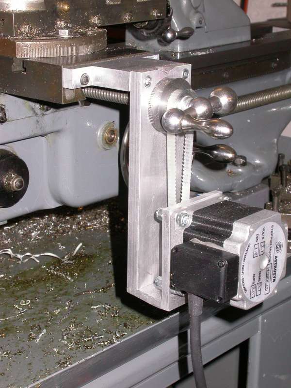
Photo 8: Motor and belt installed: side view
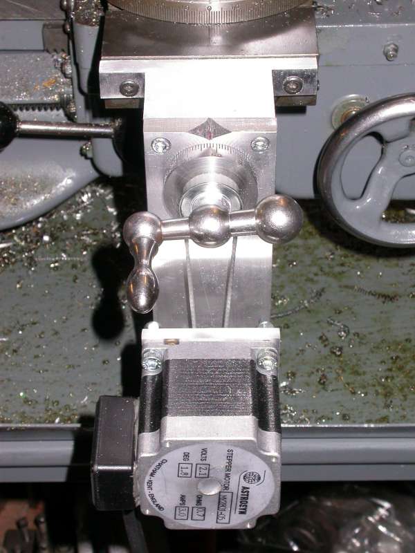
Photo 9: Motor and belt installed - top view
If all is well, the cross slide should still be operable by means of the crank handle; the stepper motor will give a slightly "notchy" feel, but it should still be easy to operate by hand. The cross-slide drive is now ready for use as soon as the threadlocker compound has been given time to cure.
Cross-slide drive performance
As with the leadscrew drive, I did some initial testing using one of my DivisionMaster controllers. In this case, I wasn't too bothered about what traverse speeds I could obtain; I had gone through this exercise before with the leadscrew, and having also seen a much smaller NEMA 17 frame motor achieve quite heavy facing cuts, as mentioned earlier, I was confident that the motor I was using would be more than adequate for the cross-slide drive. I was much more interested in the way the setup performed from the point of view of repeatability and backlash.
Using the DivisionMaster set for a 720:1 worm ratio allowed me to read the display in inches, as described in Part 1. I set up a dial indicator with its probe bearing against one of the jaws of the chuck, as shown in Photo 10, to give me an accurate indication of how the cross-slide was moving. Making repeated moves back and forth showed that there was almost exactly 1 thou of backlash in the system, which would be accounted for by play in the feed screw/nut, which is perfectly usable. On repeated moves, any inaccuracy in the final position, when approached from the same direction (i.e., move 1" in, note the dial reading, move 1" out, then 1" back in, and compare readings) was below the resolution of the dial indicator I was using. So far, so good.
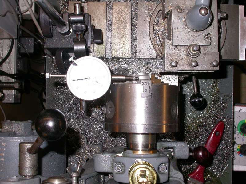
Photo 10: Testing the cross slide backlash
Using a similar setup to test repeatability and backlash on the leadscrew, with the dial indicator rotated to align with the spindle axis (see Photo 11) was a different story - I measured of the order of 10 thou of backlash, and error in the final position on repeated moves was of the order of half a thou. This told me that it was time to adjust the clasp nuts; after adjusting the three gib strip adjusting screws (on the left hand vertical edge of the saddle) for fairly stiff operation of the operating lever and minimize play between the clasp nuts and the leadscrew, and adjusting the depth screw underneath the bottom half nut to allow maximum engagement of the nuts, the repeatability was as good as the cross-slide, and the backlash was down to about two thou. I would guess that treating the lathe to a new leadscrew and clasp nuts would improve the situation even more; however, the measured performance seems to indicate that the lathe will be usable in its current form.
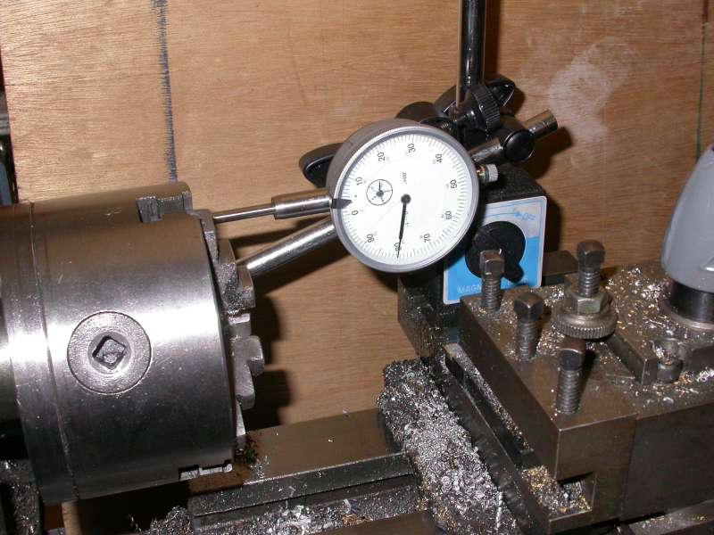
Photo 11: Testing the leadscrew backlash
If you happen to have a DivisionMaster controller to hand, or even better, two of them, the conversion so far can now be used either completely manually or using power feeds on either or both axes. Obviously, using DivisionMaster controllers is rather less convenient and much less versatile than having a fully fledged CNC control, but if your primary objective was to fit a power feed, then you would get that, with the added bonus of being able to define precise moves of either axis.
Next time
That completes the mechanical aspects of the conversion for the cross-slide. In part 3, I will describe the construction and installation of the drive circuitry, and in Part 4, the use of Mach 3 as a CNC control.
PARTS LIST
Suppliers and other contact details:
- Astrosyn International Technology PLC, The Old Courthouse, New Road Avenue, Chatham, Kent, ME4 4QJ, UK. Tel: 01634 815175 Website: http://www.astrosyn.com
- Arc Eurotrade Ltd, 10 Archdale Street, Syston, Leicester, LE7 1NA, UK. Tel: 0116 269 5693 Website: http://www.arceurotrade.co.uk
- RS Components. Tel: 01536 201201 Website: https://uk.rs-online.com/
- DivisionMaster controllers are no longer available.