Introduction
A friend presented me with what, if I had been a professional clock repairer, would probably have been a simple problem to solve; his long-case clock had a broken tooth in an idler wheel between the winding arbour of the clock and the barrel arbour. This wheel was about 16mm diameter, with 20 teeth, pressed onto a 13mm long 4mm diameter shaft. The clock itself is more of sentimental value than monetary value, as it is a fairly modern piece; even so, I was reluctant to take the obvious route of cutting out a section of the wheel, grafting in a new piece of brass, and cutting to shape; that is definitely a one-way trip, as once you have fouled up the original part, there's no way back without making a completely new part. So it seemed to me that the best approach was to make a new wheel and shaft and to leave the broken part alone, in case my efforts proved to be futile and he ended up having to find a more competent repairer.
On close inspection, the tooth form of the damaged wheel and its two neighbours from the adjacent shafts looked to me like Involute rather than the Cycloidal form traditionally used in antique clocks; a quick search through the pages of the a gear catalogue showed that the outside diameter of a 20T, 20 degree pressure angle, 0.7 module gear was a close match. So, the obvious but expensive solution would have been be to buy a conventional No.6, 0.7 module, multi-tooth gear cutter and whiz off a 20T gear. However, the fact that I didn't particularly want/need a No.6, 0.7 module gear cutter for any other purpose made me look for other solutions.
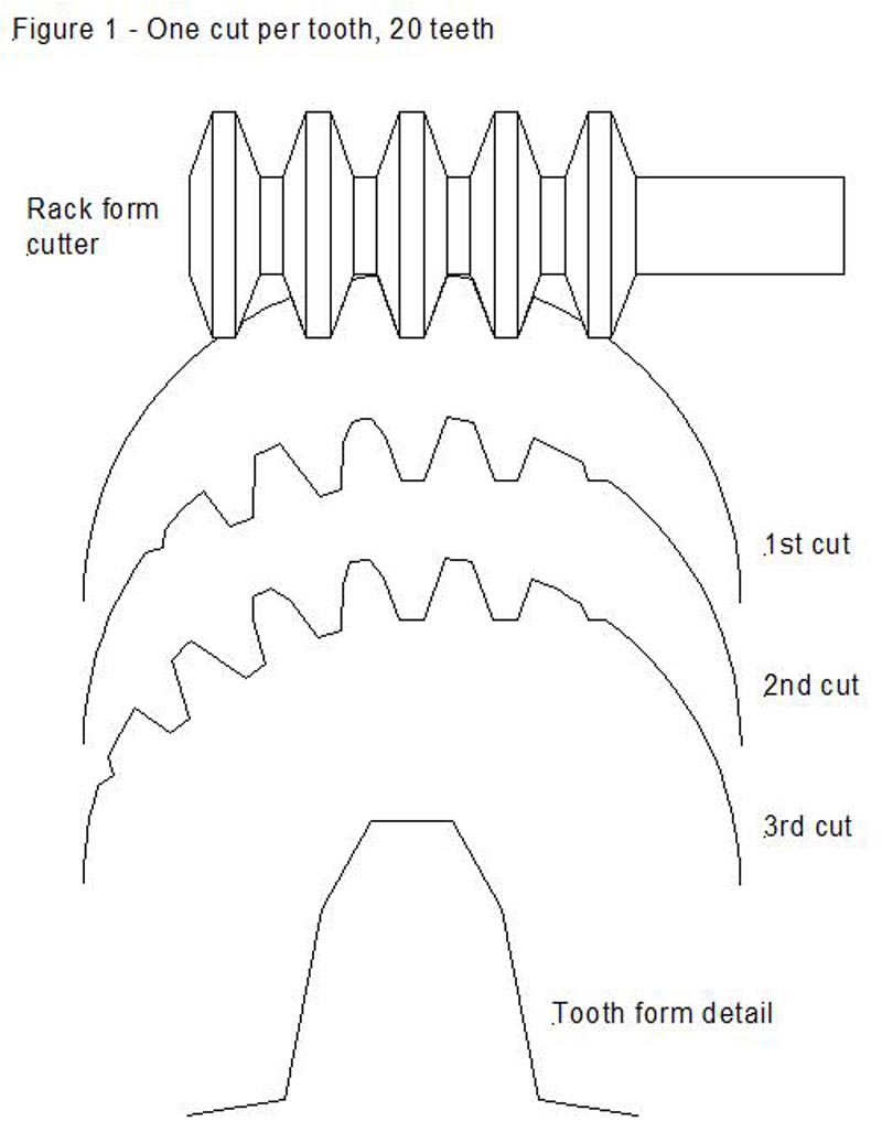
I have had many conversations with John Stevenson over the years on a wide range of engineering topics, and I recalled one such conversation on the subject of gear cutting using CNC, where John was describing the old Sunderland gear cutting machines that use a "planning" technique with a rack form cutter, and suggested that this technique might lend itself to adaptation for CNC. After a cutting stroke, the gear blank is rotated a small amount, and the cutter is advanced in the same direction, along a tangent to the circumference of the blank, by a corresponding small amount. This process is repeated until the blank has rotated by a full tooth, at which point the rack is moved back by a tooth position and the process starts again. This results in a near-perfect generated Involute gear form - because the cutting involves discrete steps, the surface of each tooth will actually be a number of facets; however, make the number of cuts per tooth large enough and this isn't an issue. The CNC connection here was that it would be straightforward to make up a single point fly cutter with the right rack tooth form, and the coordinated movements would be easy to achieve using CNC; hence, for the investment of time needed to grind up a single point cutter with the right dimensions for a given module size, you could readily cut gears with any number of teeth from not very many right through to rack.
Talking the problem through with John, he suggested an alternative method that would lend itself to more conventional gear cutting approaches. Instead of a single point fly cutter, it wouldn't be hard to make a cylindrical cutter with a rack tooth form - this would at first sight look rather like a hob, but instead of generating the teeth by screwcutting at the correct pitch for the rack, you take a series of plunge cuts with a rack-form lathe tool, the cuts spaced apart by the module size of the desired rack. In other words, the basic cutter looks like a rack that has been wrapped around a cylinder. Cutting teeth can then be formed by gashing, hardening, and finally honing of the cutting edge. And yes, if you want to go the whole hog and form-relieve the cutting teeth, you could do that too, although for my purposes, cutting a gear in brass, it seemed likely that I could get away without bothering with that refinement.
The appeal to me of this approach was that I wouldn't even have to think about the CNC programming needed to do the "proper" job (although in reality, this should be fairly simple) - instead, I could press my "CNC gear cutting engine" into service (described in MEW issue 96), which makes use of a stepper-motor driven dividing head, and still get the desired result. For practical purposes, the technique would be the same as using a conventional multi-tooth gear cutter; you take a cut, advance the blank 1 tooth, take a cut - etc., with the difference that the cutter would cut (parts of) more than one tooth at the same time. How many teeth the cutter will span depends on the tooth count of the gear being cut - the more teeth, hopefully the more accurate the final tooth form would be, as the cutting action would more closely emulate the action of the "shaping" approach. Attempting this with a 20 tooth gear seemed a bit of a stretch, but I thought it was interesting enough as an idea to give it a try, and in the particular application to hand, accuracy of tooth form wasn't a big consideration as long as the final gear would mesh well enough with the existing gears.
Tooth form
Figure 1 shows diagrammatically the progress of cutting when using a cutter of the form described, taking cuts to full depth, and rotating the blank a full tooth per cut, and also shows the resultant tooth form. One of the things that surprised me (maybe it shouldn't have if I had thought about it more) is that only the central cutting tooth and the adjacent flanks of its two neighbours do any real work when cutting a low-count wheel - the final tooth form is basically formed by just two facets on each of the flanks of the teeth. The root of the tooth is the basic rack form, but the tip of the tooth is a little narrower.
If you increase the tooth count to 40 teeth (Figure 2), you start to detect a bit of undercutting at the base of the teeth, and this will increase as the tooth count gets larger.
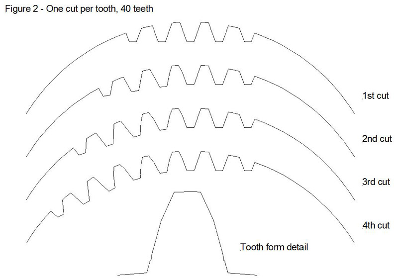
Figure 3 shows what happens if you take two cuts per tooth-space on a 20 tooth blank - the first cut with the cutter at the central starting position, as in Figure 1, and the second after rotating the blank by ½ a tooth position and advancing the cutter in the same direction, along a tangent to the circumference of the blank, by ½ the linear pitch of the rack (the linear pitch being equal to pi times the module size in mm). The detail of the tooth form shows that this produces a much closer approximation to the correct Involute form, and again, shows the beginnings of some undercutting at the base of the tooth.
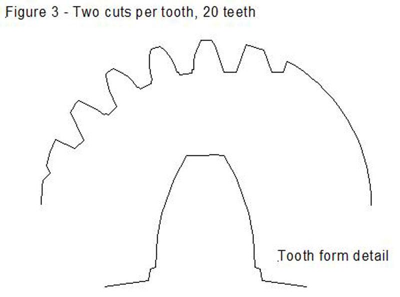
Figure 4 shows the results of doing 4 cuts per tooth, and clearly demonstrates what one would expect, that the more cuts you take per tooth the nearer the tooth form will get to the correct generated form.
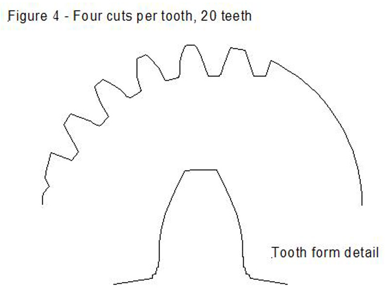
What these diagrams illustrate is that this is a gear cutting technique that can potentially be adjusted to suit the application and the time available; in some cases, a single cut per tooth will be "good enough" (as was the case in my application - the wheel that I cut using this method is now installed in the clock's winding train and works just fine); in others, increasing the number of cuts per tooth will give a more accurate, and appropriate, result. In practice, to do N cuts per tooth, you would probably start by cutting all of the teeth at an initial setting, using the "one cut per tooth" approach, keeping the cutter position constant and advancing the blank one tooth per cut. You would then advance the dividing head by 1/Nth of a tooth, and the cutter by 1/Nth of the linear pitch, and then go round the wheel again, repeating the process for N cuts per tooth in total. This is potentially fairly tedious if N is large and you are using a manual dividing head, but on the other hand, making the cutters is easy to do and most importantly, cheap.
Theoretical cutter dimensions
The technique described here uses a single-point form tool to cut the grooves in a cylindrical cutter, and in turn, the cylindrical cutter is used, in place of a conventional multi-tooth gear cutter, to cut the final gear teeth. It follows that the single-point form tool should be an accurate replica of one tooth of a rack made to the appropriate module size (a rack being just a gear with an infinite number of teeth).
Chapter 7 of Ivan Law's excellent book "Gears and Gear Cutting" (number 17 in the Workshop Practice series) describes the formulae necessary to calculate the tooth proportions and depth of cut, and these can be used to work out the proportions of the corresponding form tool. In my first "stab" at this, I cheated and used the table at the bottom of page 88 of the book, which is strictly speaking intended as a table of dimensions for a single point cutter to cut a worm to mesh with an Involute spur gear; in practice, this proved to be close enough, although probably not entirely correct for what I was doing. When interpreting that particular table, please note that the table's headings got messed up in the typesetting, so careful reading is required!
Using the discussion in Chapter3 and the formulae in Chapter 7, one reaches the following conclusions:
D (the depth of an Involute gear tooth) is exactly twice the module size.
However, the teeth are cut slightly deeper than this to allow an additional clearance, f, at the base of the tooth; Ivan's book gives f as 1/20th of the circular pitch. As the circular pitch (or in the case of a rack, linear pitch) of a module gear is pi times the module size:
D+f is 2.157 x (module size).
D+f is the total length of the tooth, and is therefore also the total depth of the tooth space (measured from the OD of the gear), so this is also the depth of cut necessary when cutting the grooves in the cylindrical cutter, and the depth of cut necessary when using the final cutter to cut a gear. So, in my case, cutting a 0.7 module gear, D+f should be 1.51mm. This is the same as the figure quoted in the table at the bottom of page 88.
The width of the tooth at the pitch circle diameter should be equal to pi/2 x (module size). Therefore, the width of the tip of the rack tooth (and therefore the tip width of the form tool) should be:
((pi/2)-0.739) x (module size) for a 20-degree pressure angle, or
((pi/2)-0.517) x (module size) for a 14.5-degree pressure angle.
For my 0.7 module, 20-degree pressure angle gear, this gives a tip width of 0.58mm, which is rather wider than the 0.51mm quoted in the table. I believe the difference here is simply a reflection of the fact that the table is intended for a different purpose - cutting a worm, rather than cutting a groove in a gear cutter.
Making the cutter
The first step is to make the single point lathe tool with the appropriate tip shape to cut a rack of the right module size. I used a length of 1/8" diameter HSS to make my lathe tool, and temporarily converted my Taig lathe to a cutter grinder for the purpose. I already had a rather crude boring bar holder that I was able to press into service to hold the HSS blank, as can be seen in Photo 1; I made up a collet to hold the HSS blank that allowed me to rotate the blank either side of horizontal to get the necessary relief on the cutting edges of the tool.
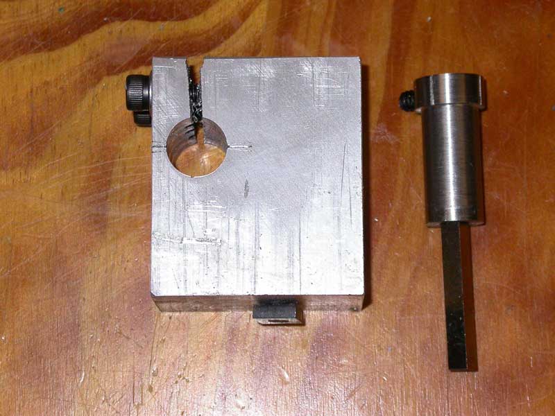
Photo 1 - Boring bar holder adapted to hold cutter blank
Photo 2 shows the holder in position, with a paper 20-degree "protractor" to set the angle of cut.
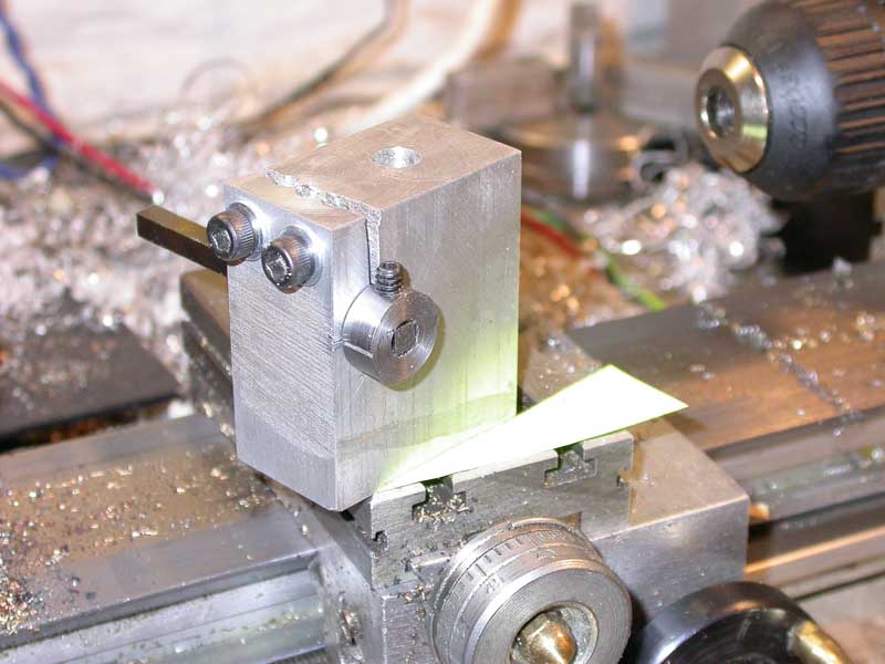
Photo 2
Photo 3 shows the flanks of the cutter being ground, using a cup wheel mounted on the Taig spindle.
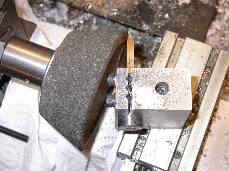
Photo 3
The blank was ground to a sharp point, and then the tip accurately ground off to give the right tip width - a bit of elementary Trig gives the amount of infeed necessary to grind off the point and give the right tip width:
Infeed = (tip width) x 1.374 (for a 20 degree pressure angle), or
Infeed = (tip width) x 1.933 (for a 14.5 degree pressure angle)
A dial gauge touching on the saddle allows the infeed to be measured accurately (Photo 4); adjust the setup so that the sharp tip of the cutter is just touching the grinding wheel, zero the dial gauge, and feed the cutter into the wheel by the required amount.
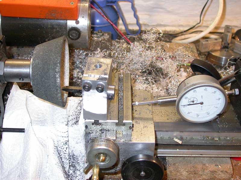
Photo 4
The next stage is to cut the grooves in the rotary cutter, using this lathe tool. Photo 5 shows this in progress; I ended up making a 7-tooth "rack", overkill given the conclusions I reached later when drawing up the diagrams (see "tooth form" above); in practice, there is little point in making the "rack" longer than 3 teeth. The lathe tool proved to work very well, giving clean chatter-free cuts in the silver steel bar I used for the cutter. The spacing of the cuts is exactly the circular pitch in mm corresponding to the module size of the cutter, 2.2mm in the case of my 0.7 module cutter.
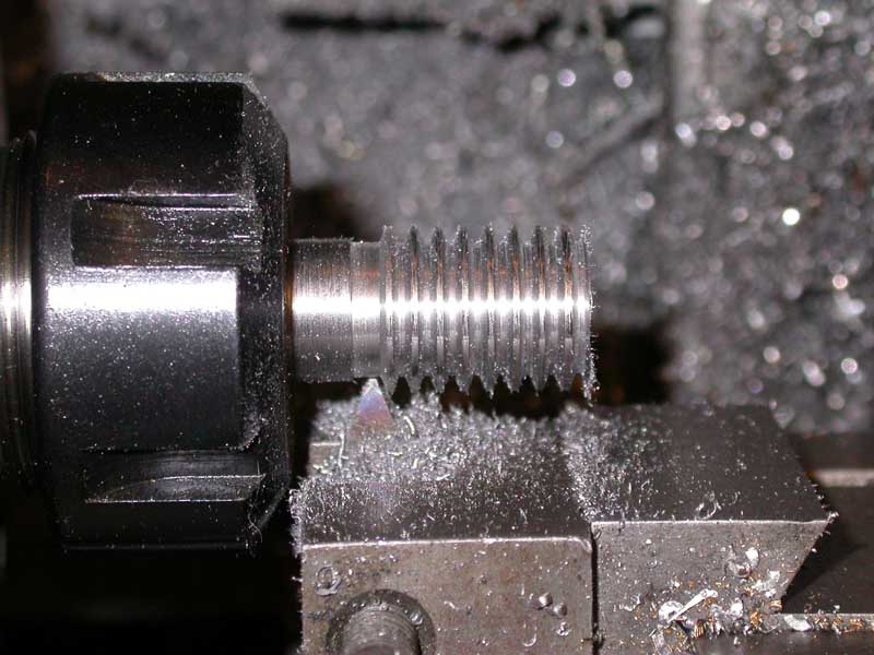
Photo 5
Photo 6 shows the cutter after "gashing" with 8 longitudinal cuts to below the bottom of the "rack" grooves - this was done by hand using a Dremel fitted with an abrasive disk, and is rather crude, but it did the job all the same. After hardening the cutter in the usual manner , a final lick with the Dremel gave very serviceable cutting edges on the teeth. I didn't bother to temper the tool at all, on the basis that the heat generated by the final honing of the cutting edges and taking the first cut would do this for me, and in any case, cutting leaded brass with this kind of tool would be unlikely to damage a "glass-hard" cutter.
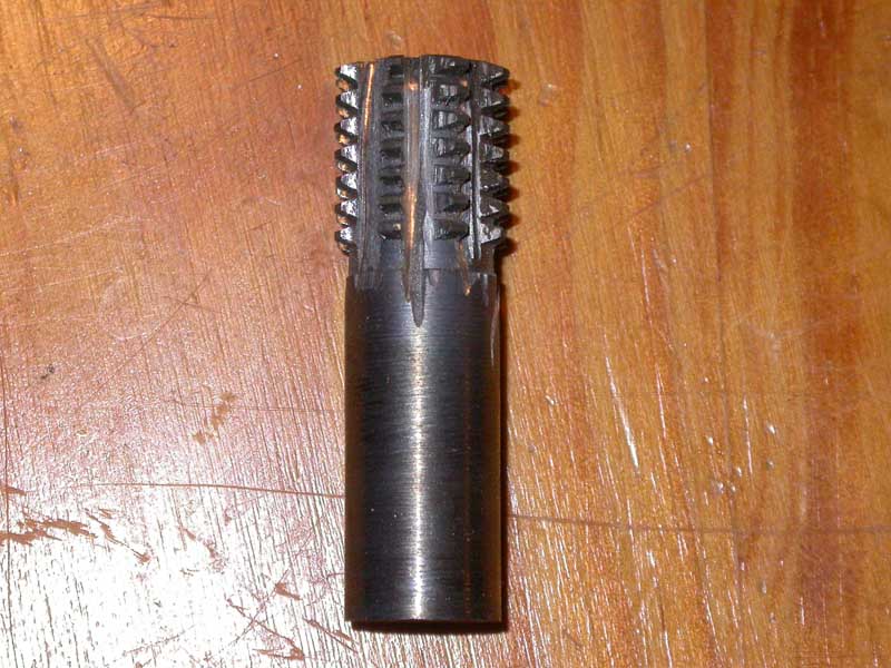
Photo 6
Cutting the wheel
Photo 7 shows the cutter and the wheel blank set up in my wheel cutting engine. I positioned the blank so that its axis of rotation lined up with the central tooth of the cutter, as can be seen in the photo.
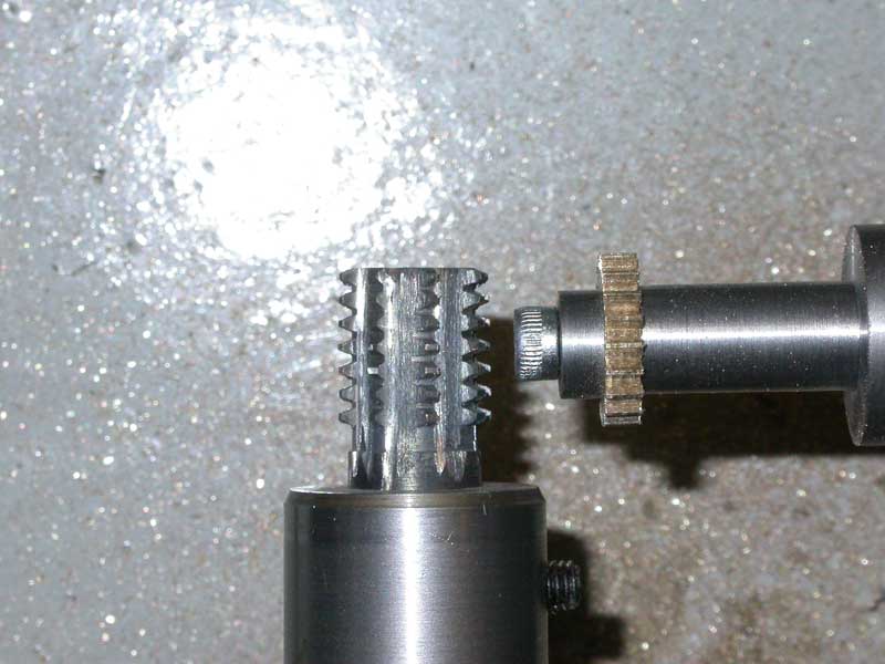
Photo 7
Photo 8 shows the overall arrangement of the wheel cutting engine - this is based on Peatol/Taig lathe components (see MEW issue 96, and also this page), with the cross slide giving movement to align the blank and cutter, the vertical slide to control cut depth, and the saddle traverse allowing the blank to be passed across the top of the cutter. The dividing head is stepper-motor driven, controlled by one of my DivisionMaster controllers (available through Model Engineers Digital Workshop), and steps on automatically when the saddle is moved to the right against a limit switch. However, there's no reason why a similar approach shouldn't be taken using conventional manual dividing techniques.
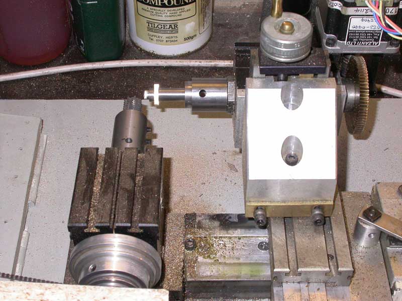
Photo 8
Photo 9 shows the resultant 20-tooth gear (right) and the original broken gear (left). The photo shows clearly the fact that each tooth is basically 5-sided (two facets on each flank and a square top); however, in practice it meshed very well with the original gears on either side, which was the important point.
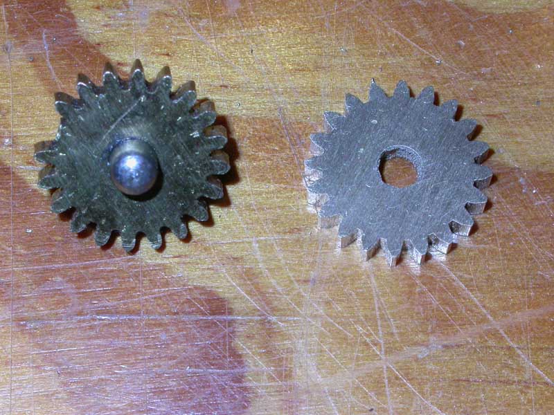
Photo 9
Photo 10 shows the new gear with its shaft in place in its plate, meshing with one of its neighbours.
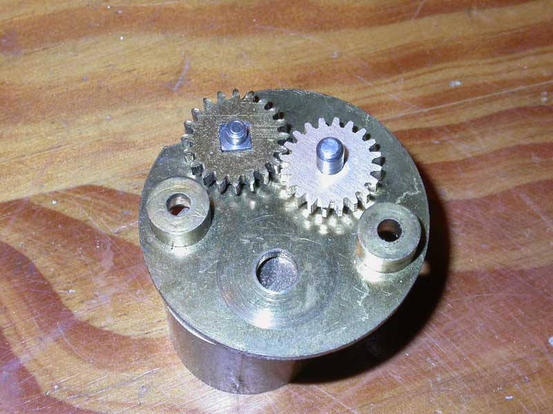
Photo 10
Conclusions
This approach has the benefit of allowing a gear cutter for the desired module size to be made very simply, using materials to hand in the workshop. While the cutter as described may not prove to be entirely satisfactory for cutting harder materials, due to the lack of "form relief" on the cutting edges, the cutter works very well in softer materials such as brass and aluminium.
The "one cut per tooth" technique, while not generating the ideal Involute tooth form, produces a tooth form that can actually work where the application doesn't require critical accuracy. However, by increasing the number of cuts per tooth, as described, it is possible to approach more and more closely to the ideal Involute tooth form, so the degree of accuracy of the final tooth form can be adjusted if necessary to suit a more critical application. For those with access to a CNC mill, it would be a simple matter to generate the necessary "G" code that would allow this kind of cutter to be used to generate Involute gears of any tooth count, and with a highly accurate tooth form.
References
"Gears and Gear Cutting" by Ivan Law, Workshop Practice Series No. 17, ISBN 0-85242-911-8.