Introduction
In this third article, I will describe the final pieces of the jigsaw as far as the constructional phases go - building the stepper motor drive electronics, and installing spindle sensor and E-stop circuitry.
Design decisions
I chose to use Mach 3 as the control software for this conversion, in place of the DeskCNC system that I have previously used for my Taig mill conversion and the earlier X3 mill conversion. There are good reasons for this change in approach. Firstly, although there is some support within the DeskCNC system for installing a spindle encoder that would allow threading to be performed, the DeskCNC system is primarily aimed at driving a mill; one consequence of this is that there is no support within its CAM functions for turning operations. Making sense of generating G-code for turning operations from a drawing therefore takes a bit of work in DeskCNC, and ideally, needs a CAM package such as Dolphin Partmaster that is able to generate G-code for both lathe and mill operations. Mach 3, on the other hand, has been designed to properly support both lathe and mill; in particular, its built-in "wizards" provide access to most of the simple lathe operations that you are likely to need to perform (turning to a shoulder, taper turning, spherical turning, internal and external threading, taper threading-and so on) without the need for a conventional CAM system, and the "Lazy CAM" add-on to Mach provides simple CAM facilities as well.
Secondly, the Mach 3 system is under active development in a number of interesting directions, some of which are ideal for the kind of hybrid manual/CNC approach that I wanted to take with this project. In particular, it is possible to incorporate various "pendant" style devices into a Mach 3-based system that allow manual control of the lathe via a command dial, or even via a games joystick; the ability to integrate these devices with the Mach 3 software means that you can manually "jog" an axis using the control knobs on the pendant device in a way that closely mimics how you would control the lathe using its own handwheels. The Mach software translates the manual actions into appropriate motor movements for the two lathe axes, and also updates its knowledge of the position of the axes at the same time. The only way of achieving this kind of manual control under DeskCNC is to temporarily switch control from the computer to the pendant, do the manual position adjustment using the pendant controls, and then switch back; however, in the process of making the manual adjustment, the computer does not know how far the axes had been moved when under manual control, so DeskCNC's knowledge of the machine position is no longer correct.
These two reasons seemed to be sufficiently worthwhile advantages to give Mach 3 a try. Having seen some of the power and flexibility of the Mach 3 software during this project, my next step is likely to be to retrofit my two CNC mills with Mach 3!
The stepper motor drive circuitry that I chose to use in this project is similar to the stepper drive that I built for my Taig mill. As before, the drive electronics is based around 3 amp, 40V stepper motor drivers sold by Arc Eurotrade (part number SMD 093064), powered by a simple linear power supply; however, in order to use the Mach 3 software, it is necessary to interpose some interfacing electronics between the PC and the stepper drives. The reason for this is twofold. Firstly, Mach 3 uses the parallel port of a PC as the means of interfacing its inputs and outputs to the drive electronics. Unfortunately, the trend in PC design towards lower voltage and lower power devices has meant that you cannot necessarily rely on your PC's parallel port either to generate output signals at the required voltage level (nominally 5 Volts, but often only 3.3 Volts on newer systems, particularly laptops), or to be able to supply the necessary signal current to drive the stepper motor drivers. So at the very least, some form of conditioning circuitry is needed that will ensure that the proper voltage and current is available on each signal pin of the parallel port. Secondly, it is desirable to ensure that the PC and the drive system are electrically isolated from each other, to minimize the possibility of an electrical failure in the drive system also damaging the PC. In order to achieve this, it is desirable for the signals to and from the PC to be "optically isolated". These two functions, conditioning of signals to the right voltage/current requirements, and optically isolating the input and output devices, can be achieved by using what has come to be known colloquially as a "breakout board". In their simplest form, breakout boards simply connect the 25 pins on the parallel port connector to screw terminals to make them simpler to wire up; however, for our purposes, something rather more sophisticated is needed, that contains active circuitry. There are a number of suitable parallel port breakout boards available on the market that will work with Mach 3; I chose to use the Optoport board (see Photo 1), manufactured in the UK by C.R.H. Electronics Design. You can make a slight saving on the cost of this board by buying it in kit form, but for the small additional cost it is well worth buying it ready built. C.R.H. also offer simpler parallel port interface boards that are potentially suitable for this application; for example, the PBB20. This is physically smaller than the Optoport board, and has input/output buffers, but no optical isolation. With the stepper drives I chose, which already have their own opto-isolation built in, the PBB20 would be perfectly adequate; however, as the Optoport provides opto-isolation for any input signals to the PC, I decided to stick with the more comprehensive interface option. The other potentially useful capability of the Optoport board is that it has two on-board relays capable of switching mains voltage, for example allowing outputs from the PC to switch coolant pumps and spindle motors on and off.
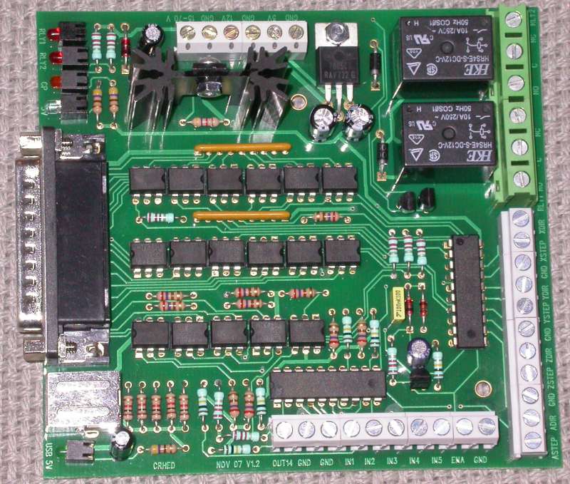
Photo 1: Optoport "breakout" board
Safety issues
Building the drive system for this project involves working with mains circuitry; if you don't consider yourself to be competent (and the word was competent, not confident!) to do this safely, please get it done by someone that is.
The CNC system that I am describing here is very capable of taking on a life of its own if its human operator tells it to do something stupid (and yes, it is generally the operator that does something stupid; the machine just does what it is told!). Mach 3 is a complex software system; from my own experiments with the working system, it is all too easy to press the start button and watch the toolpost hurtling towards the chuck at an alarming rate, and maybe see it crash into the work (or worse) before you have a chance to stop the machine. Therefore, please pay close attention to safety measures, such as emergency stop (E-stop) circuitry and the like, and don't be at all tempted to skimp in that area. I will describe later in the article how I chose to implement an E-stop circuit for my setup; however, your needs may vary, so please don't assume that what I have described is adequate for your own installation.
An important feature that the Optoport interface board offers is the ability to make use of the so-called "charge pump" output signal that can be generated by Mach 3. This is a relatively slow frequency (10 KHz I believe) signal that is output on one of the pins of the parallel port when Mach 3 is in a healthy state. The interface board converts this signal into a steady 5V DC level that is used to enable the rest of the interface electronics; if the "charge pump" signal goes away, this drops to 0V and causes the interface to/from the PC to be disabled by the interface card. This is an important piece of safety functionality; it means that if the PC should do what PCs often do, and crash, the drive hardware should immediately stop driving the stepper motors, and any other outputs from the PC that might be controlling the spindle, coolant pump, or whatever, will switch off. The charge pump output will also switch off if Mach 3 receives an E-stop input signal; operator intervention to reset the system is then required before the system will become functional again.
Parts sources
I have included a parts list at the end of the article that contains details of the major components of the system, and a contacts list that shows where to find the companies and websites mentioned in the article. Many of the electronic components are obtained from RS Components; although primarily a trade dealer, they will sell to anyone, and there are local trade counters in the larger towns and cities where you can pick up your order. However, one of the drawbacks with RS is that some of the cheaper components come in packs of 5 or 10, and cable often comes in 30 metre drums, so buying from them can mean that you end up with spare components at the end. This is fine if, like me, you are likely to find a use later on; however, you may decide that finding alternative sources is desirable. Obvious candidates there are local electronics suppliers, and suppliers more targeted at the enthusiast, such as Maplin. If you decide to source components elsewhere, make sure that they are at least to the minimum specification of the components shown on the RS site.
Mounting the drive system components
As with my two previous CNC conversions I used a box supplied by RS to house the stepper drive circuitry. This is a long, slim, grey box, 430x150x50mm, and neatly houses two stepper drives, the power supply, and the Optoport interface board. Photo 2 shows the layout of the components, all of which are attached to the "lid" of the box; this has the distinct advantage that the drive electronics can be completely removed from the lathe for bench testing if need be. Photos 3, 4, and 5 show the extent of the metalworking that is required:
- Holes for the IEC mains inlet socket, the power switch, and the fuse holder (Photo 3);
- A hole for the 9-pin D-type connector, and a slot for the two connectors on the Optoport board to be accessible - a D25 parallel port connector and a USB socket (Photo 4);
- Two 25mm diameter holes for the panel mounted 4-pin XLR sockets that will serve as connections for the cables to the motors (Photo 5). I used sheet metal punches for this as I happened to have one the right size. The sockets are held in place with a couple of self-tappers. XLR plugs/sockets are excellent for this application; the pins are good for 15A DC, the plugs are robust, and there is a locking mechanism to prevent inadvertent disconnection of the motors, which can spell death for some drives if this happens with the power turned on.
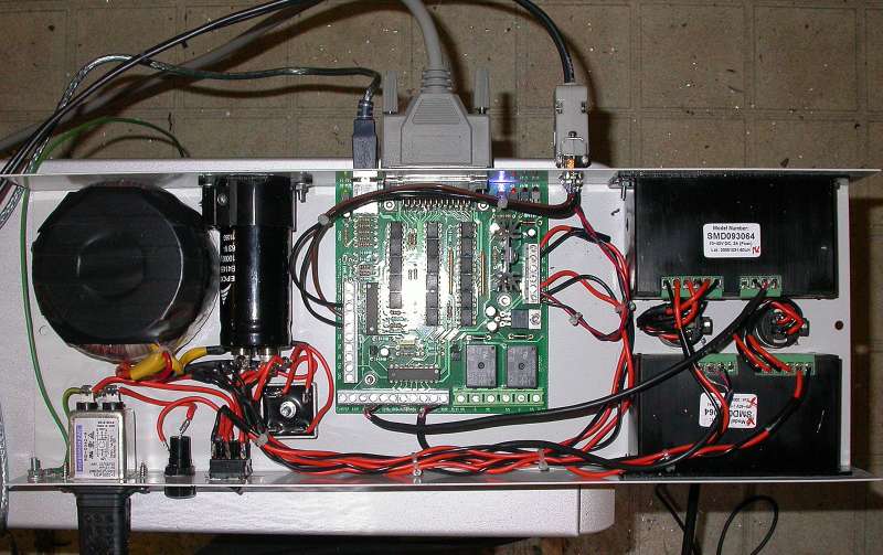
Photo 2: Component layout
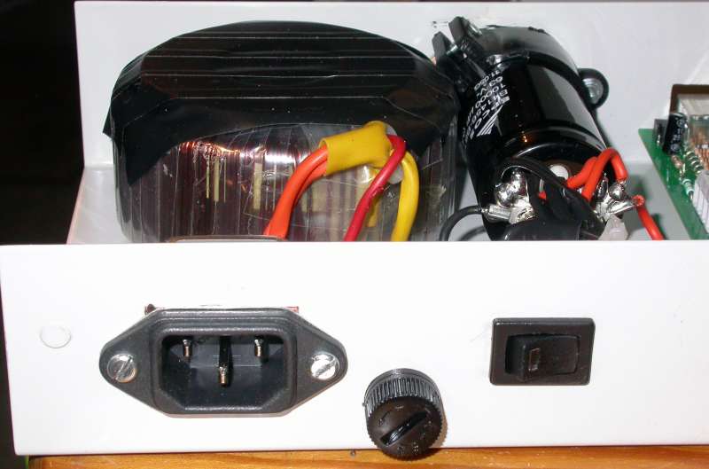
Photo 3: Mains socket, fuse, and switch positions
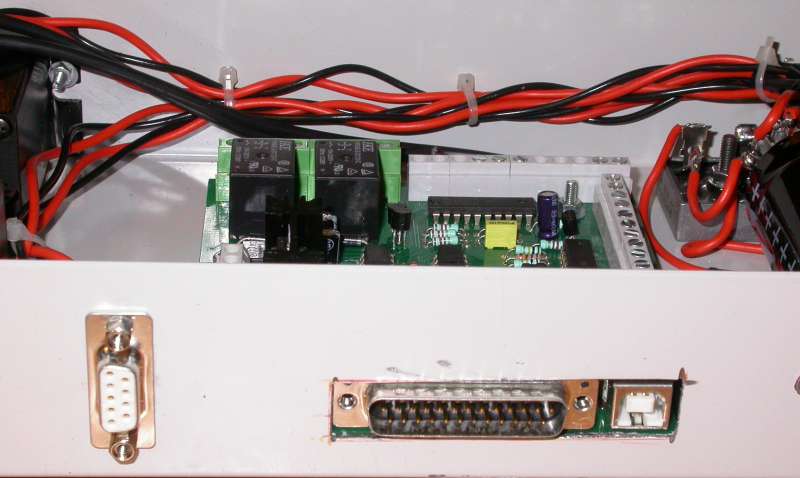
Photo 4: Signal socket positions
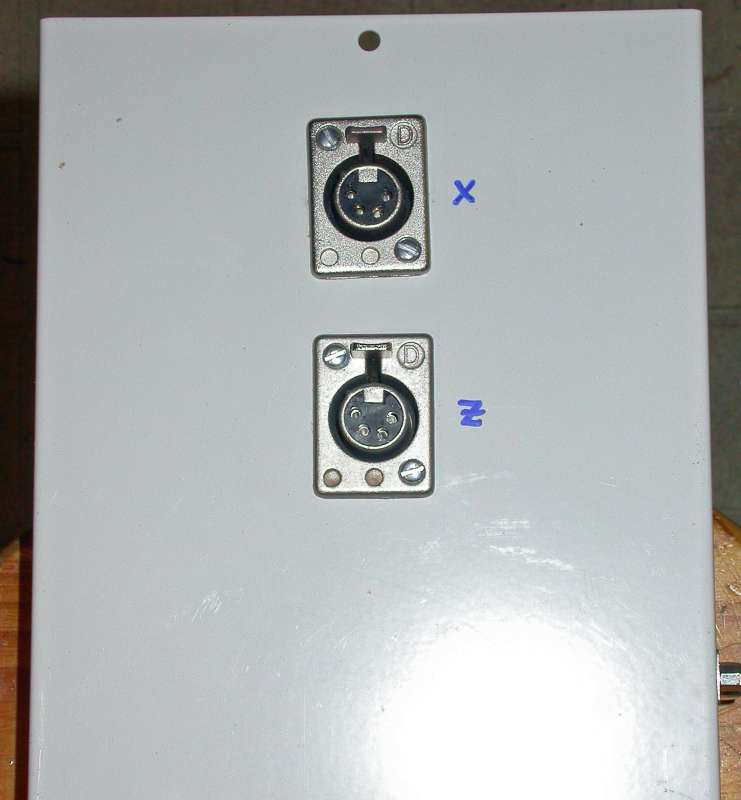
Photo 5: XLR socket positions
The slot for the Optoport connectors and the holes for the switch and IEC socket were cut using a Dremel-style device fitted with thin abrasive cutting discs. This is an effective, if somewhat crude, way of cutting holes in sheet metal, but I would advise doing it out of doors; I got through several of these discs in the process, and had a lot of cleaning up to do afterwards to get rid of the nasty layer of dust that covered my workbench. It is worth getting all of the metalwork and component mounting done before starting to wire the components together; the layout isn't terribly critical, so a simple approach of placing the components in their positions and marking with felt pen works very well. As can be seen in Photo 2, the power supply components are located at one end of the lid, the Optoport board roughly in the middle, and the two stepper drives at the other end, with the two XLR sockets located in the space between the drives.
The stepper drives are held in place with a couple of M3 screws and nuts; it is worth setting the switches on these drives before fixing them in position, as it is a bit of a fiddle to do it later. Photo 6 shows the switch settings; the microstep switches are set for 8 microsteps, and the motor current is set for 2.4A, which is the right setting for the Arc Eurotrade motor that is fitted to the leadscrew (Z axis). For the Astrosyn motor I used for the cross-slide (X axis), the current setting should be 3A, i.e., all of the current setting switches to the right. If these drives are mounted with the connectors at the top, the wiring up can be done with the drives in place, which makes life simpler.
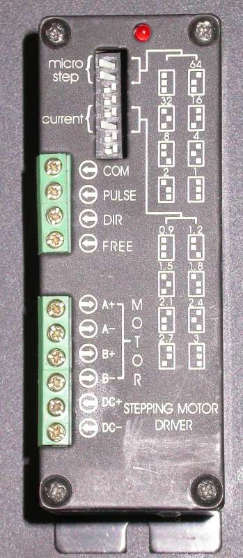
Photo 6: Stepper drive switch settings
The Optoport board is mounted on two stand-offs made by fitting a pair of M3 countersunk screws in holes drilled through the case and through the two mounting holes on the board, using additional nuts between the case and the board to lift it into the right position. I also used a couple of Nylon washers to insulate the board tracks from the nuts. The D9 socket is mounted using a pair of locking posts and nuts behind.
The electrolytic capacitor is held in a plastic clamp, which in turn is attached to the side of the lid with M3 screws/nuts. The transformer is a torroidal type, and is held in place with a metal disc and a single through bolt; two rubber washers are also supplied with the transformer, one goes under the transformer and the other between the washer and the clamping plate. Care should be taken to make sure that the mounting bolt and plate is insulated so that it cannot short onto the other half of the case; I used insulating tape for this (as can be seen in the photo). A short of this kind would create what is effectively a single shorted turn "secondary" winding though the transformer, which would have unpleasant consequences (low voltage, very high current, so things would start to melt!) The bridge rectifier is held in place with a single through bolt. The power switch is a press-fit into its rectangular hole.
The IEC power socket is held in place with a couple of self-tappers; this is a rather superior socket as it incorporates its own EMC filter, and will therefore help isolate the drive from external mains-borne interference, and also prevent any interference it generates from being injected into the mains. Finally, the fuse holder is held in place with its own plastic nut.
The power supply
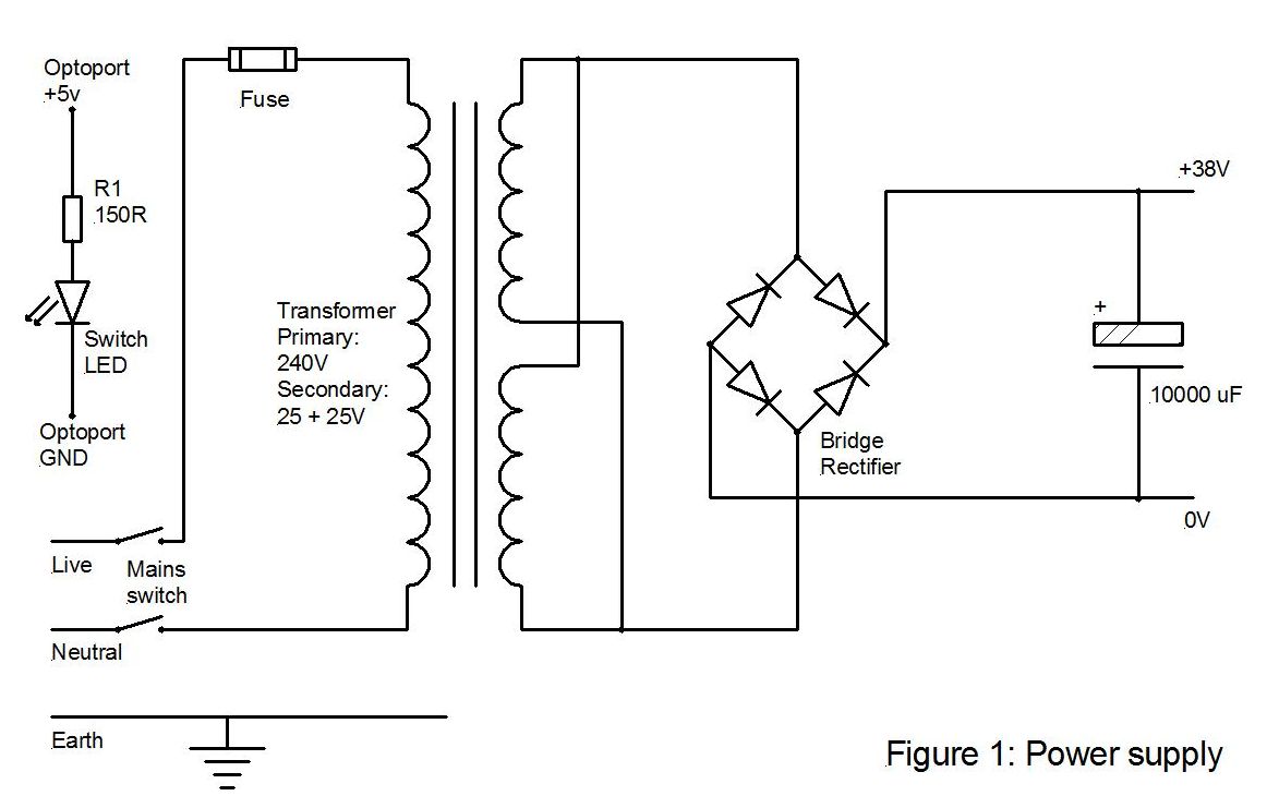
All that is needed for a stepper drive power supply is a simple "linear" supply - a mains transformer, with the secondary feeding a bridge rectifier, and the DC output is then smoothed by means of a large electrolytic capacitor. The output voltage must not exceed the 40V rated voltage of the stepper drives; hence my choice of a transformer with 25V secondaries that, when wired in parallel, rectified, and smoothed, should give a comfortable 38V DC output.
Figure 1 shows the power supply circuit diagram. The 150 Ohm resistor, R1, in series with the green mains switch LED, is chosen such that the current through the LED will be 20 milliamps when powered by the 5V available from the Optoport board's on-board voltage regulator. The terminals on the switch that connect to the LED are conveniently copper coloured as opposed to the silver terminals that switch the mains; I incorporated the resistor in the lead from the switch to the +5V output terminal on the Optoport board, and covered it in heat shrink sleeving to insulate it. It is necessary to connect the terminals the right way round; if you hold the switch with the pins facing you and the copper coloured pins at the top, then the left hand copper pin is the one that goes to the GND pin on the Optoport board, and the right hand one connects to the resistor, which in turn goes to +5V.
The rest of the wiring for the power supply is pretty straightforward; however, take care to connect the bridge rectifier correctly, and the electrolytic capacitor has to be connected with the right polarity also. Note that the mains earth must be connected to the earth screw that is welded into one corner of the box lid; there is a matching screw on the base half of the box, and I strapped the two together with a flying lead terminated in a solder tag that can be fitted to the base earthing point before final assembly.
Note that the DC output of the power supply is "floating" - i.e., it is not grounded to the mains earth; this is intentional, as it offers fewer opportunities to construct noisy "earth loops" between the drive system and the PC that will be generating the drive signals.
Once the connections have all been made, power up the power supply to make sure that all is well before continuing with the wiring up of the drives.
Drive power and motor socket wiring
The power and motor connections are illustrated in Figure 2. The power supply smoothing capacitor is fitted with screw terminals; these make a very useful connection point for connecting the DC supply to the two stepper drives. The 0V and +38V lines (- and + connections on the capacitor, respectively) should be individually connected from the capacitor terminals to each drive - i.e., use a "star" wiring arrangement rather than "daisy-chaining" the power from drive to drive. I used solder tags on these wires at the capacitor end and used reasonably heavy gauge stranded wire for the connections. Keep the wires reasonably short and use cable ties to keep them tidy; these connections can be seen in Photo 2 as the twisted black and red wires running from the power supply to the drives. The relevant connections on the drives are the terminals marked "DC+" (which is connected to the + terminal of the capacitor) and "DC-" (connected to the - terminal of the capacitor).
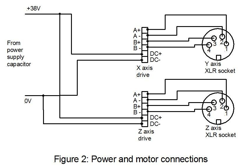
Use a similar gauge of wire to the one you used for the power connections; ideally, choose four different colours so that you can't get confused about which connection is which, and connect wires to the four motor terminals on one of the drives - the terminals are marked "A+", "A-", "B+", and "B-". Cut these wires to length so that they will conveniently reach one of the XLR sockets, and solder the ends of the wires into the solder buckets on the back of the socket. I have chosen to adopt the same wiring scheme that I used on the Divisionmaster controller for this, so that I can interchange motors between controllers; basically, this scheme connects drive A+ to XLR pin 1, drive A- to XLR pin 2, drive B+ to XLR pin 3 and drive B- to pin XLR 4. It is essential to be consistent in how this wiring is done; get it wrong and you may damage the output stages of the drives by connecting the motor coils the wrong way. Repeat the process for the other two drives.
The +38V and 0V lines from the power supply are also connected to the "15-70V" and "GND" terminals of the Optoport board, respectively, again using solder tags to fit the screw terminals on the power supply capacitor. The Optoport board has two on-board voltage regulators; one supplied 5V and the other 12V. The 5V regulated supply from the board is used to drive the LED in the mains switch, and also to power the spindle sensor described later in the article.
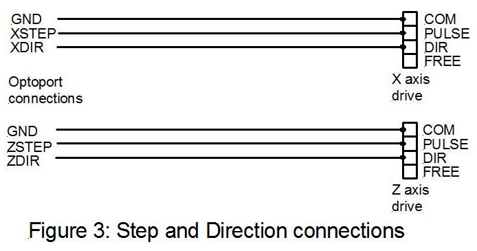
Step and direction connections
The screen printing on the Optoport board indicates where the step and direction signals appear at the various sets of screw terminals. The board is marked for the four axes, X, Y, Z, and A, that would be used on a mill; the lathe uses only the X and the Z axes, for cross-slide and saddle movements respectively. For each axis, there is a STEP and a DIR (direction) output terminal on the board, and interspersed between the axes are GND terminals. Use a shielded twin core cable for these connections; the outer shield goes to the nearest GND terminal on the Optoport board, and the two inner cores are used for the step and direction signals. These are connected at the other end to the COM, PULSE, and DIR screw terminals on the stepper drive. Again, it is worth being consistent with your use of the inner core colours, so that you can be sure that the signals reach the right terminals on the stepper drives. These connections are illustrated in Figure 3.
Sensor and E-Stop wiring
The D9 connector is used to carry external signals to the Optoport board and from there to the PC. There are two signals that are necessary; firstly, a sensor signal that tells Mach 3 how fast the lathe spindle is spinning, and secondly, a pair of pins are used for the contacts that generate the E-Stop signal. As the sensor needs power to operate, +5V and GND connections for the sensor are also provided on the D9. The D9 pin assignments, and the corresponding terminal on the Optoport board, are shown in the following table:
As these input signals are fed through opto-isolators on the Optoport board before being fed into the PC, it is necessary for the PC to provide the power to drive these input opto-isolators. This is achieved by means of a standard USB cable (the kind that has a flat rectangular plug at one end and an almost square plug at the other) that is connected between the Optoport board and any free USB socket on the PC.
The sensor provides a single pulse per rev of the lathe spindle; Mach 3 times the intervals between successive pulses, and uses the timing information to display the measured RPM of the spindle on the screen, and also to determine the pulse rate that is required on the Z axis in order to synchronize the saddle movements for thread cutting. There are many ways to generate a suitable pulse train; for example, the optical sensors that I used for the RevMaster RPM meter (MEW issues 115 & 116) would work perfectly well in this application. However, as I happened to have some Hall-effect switches to hand, I decided to try one to see whether it did the job.
Hall-effect devices are capable of detecting a magnetic field; this particular device, the Allegro A1101, is in effect a magnetically operated switch. In order to make use of it, you need to attach a magnet to some suitable part of the spindle, such that as it rotates it can be made to come close enough to the A1101 for the switch to operate. The most convenient place on my ML7 was the thrust bearing adjusting collar at the left-hand end of the spindle; I also had to hand some 9mm diameter Neodymium disc magnets that would do very well as actuators. Photo 7 shows the magnet in place on the collar; I simply filed a flat for it to sit on, cleaned the flat and the magnet, and fixed it in position with a drop of Superglue. In reality, the magnets are strong enough to hold in position on their own, but the glue makes sure that there is no possibility of accidentally dislodging it. The Hall-effect switch responds only to the North pole of the magnet, so please make sure that it is the South pole that attaches the magnet to the collar; you can find which is which either by testing the switch to see which end activates it, or by using a compass and determining which side of the magnet attracts the South end of the compass needle.
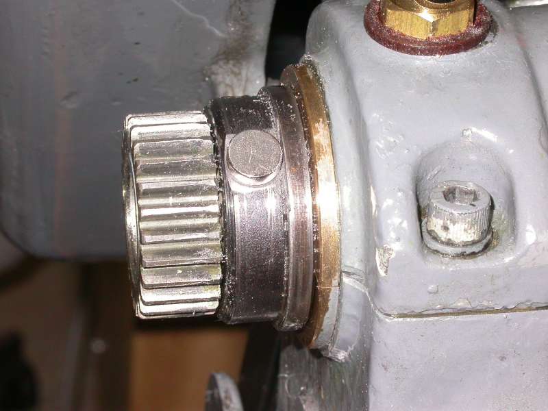
Photo 7: Sensor magnet position
Photos 8 and 9 show the sensor circuitry fixed in place, using the tumbler reverse pivot pin as a mounting bracket, and a bent strip of aluminium to support the sensor components on a small piece of strip board. Figure 4 shows the circuit diagram for the sensor; a length of two-core shielded cable is used to feed it with power and to carry the signal back to the D9 socket on the controller case, via a D9 plug. Implementing this on "Vero" or similar stripboard is a trivial exercise; you mount the A1101 device at one end of the board so that it can be held close to the rotating magnet. The only real point to bear in mind, apart from making sure the A1101 is connected the right way round, is to make sure that any mounting arrangements don't short out the tracks or ground them to the lathe. The A1101 is a 3-legged device rather like a small transistor in appearance. One side is flat; the other is chamfered on two edges. If the device is held with the chamfered side towards you, legs pointing down, then the legs on the device correspond directly to the pin numbers on the diagram; i.e., pin number1 on the diagram corresponds to the left-most leg on the device, and so on.
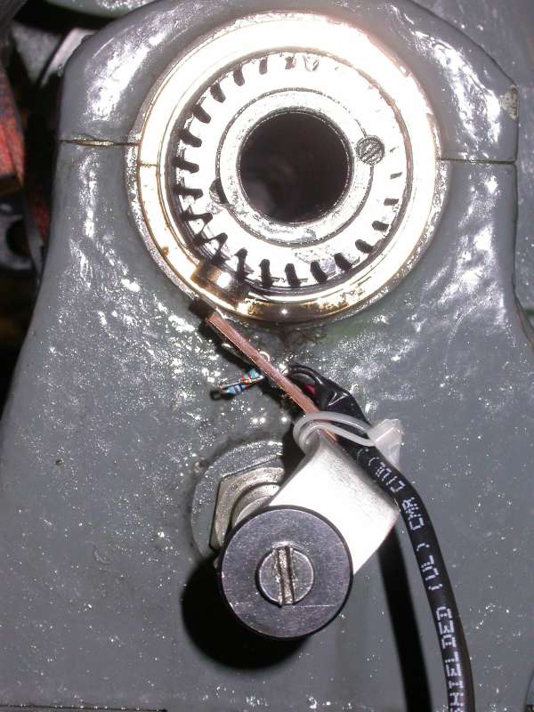
Photo 8: Sensor positioned in proximity to the magnet
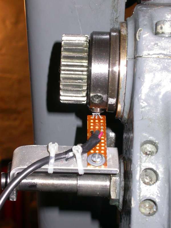
Photo 9: Sensor positioning
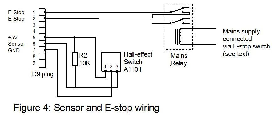
I implemented the E-stop function by making use of a mains powered relay wired into the E-stop circuitry for the variable speed drive (this is a Newton-Tesla variable frequency 3-phase drive). The principle is very simple; when the lathe is running, mains is supplied to the VFD, and I use this same mains supply to energise a mains voltage relay. When the latching E-stop button on the Newton-Tesla drive is pressed home, the mains supply to the VVFD is switched off, and the mains relay is consequently de-energised. The relay has two pairs of change-over contacts on it; one of the "normally open" contacts (open circuit when the relay is not powered) is used so that when the E-stop button is pressed, the relay contacts go open-circuit. The contacts are connected back to the D9 plug by another length of screened cable, so that when the contacts are closed (the running condition) this causes IN2 to be connected to GND, so the signal on IN2 is 0V. When E-stop is activated, IN2 is no longer connected to GND, and as it has a built-in pull-up resistor on board, it will float to 5V. The wiring from the relay to the D9 plug is also described in Figure 4.
Obviously, if your lathe is not fitted with a Newton-Tesla drive, the switching configuration may be different; however, whatever set-up you currently have, if there isn't already an emergency stop button fitted (one that latches in the "off" position, so that a deliberate action has to be taken to turn it back on, and one that is separate from the switch that you normally use to start/stop the lathe motor) it is a smart move to fit one. With the E-stop wiring described, you would then have a means of stopping both the lathe and the control system by hitting a single "off" switch. Later on, I will describe how Mach 3 is configured to use this signal on IN2 to activate the software side of the E-stop function, which in turn, causes the "charge pump" signal to go low, disabling the interface board.
LCD screen platform and drive box mounting
I chose to mount the drive box onto the back of the lathe cabinet, as shown in Photo 10, as part of the mounting arrangement for the LCD screen for the Mach 3 PC system. I started by attaching two vertical strips of 2" X 1" timber to the back of the cabinet, and a 7" wide MDF plate screwed on top of the strips. The sides of this timber bracket then served as a support for four lengths of box-section steel tubing from the metal racks at B&Q; a simple MDF and timber plate, about 12" X 8", is attached to the top of these steel tubes, and serves as a platform for the computer's LCD screen. This was all arranged to that the final height of the screen was nicely at eye height, with the screen positioned behind the tailstock end of the bed. Photos 11 and 12 show the arrangement from the side and the front of the machine. It is advisable to attach the screen base to the platform in some way so that it can't vibrate off the edge; the simplest solution here is a couple of drill holes through the mounting "foot" of the screen and a couple of wood screws.
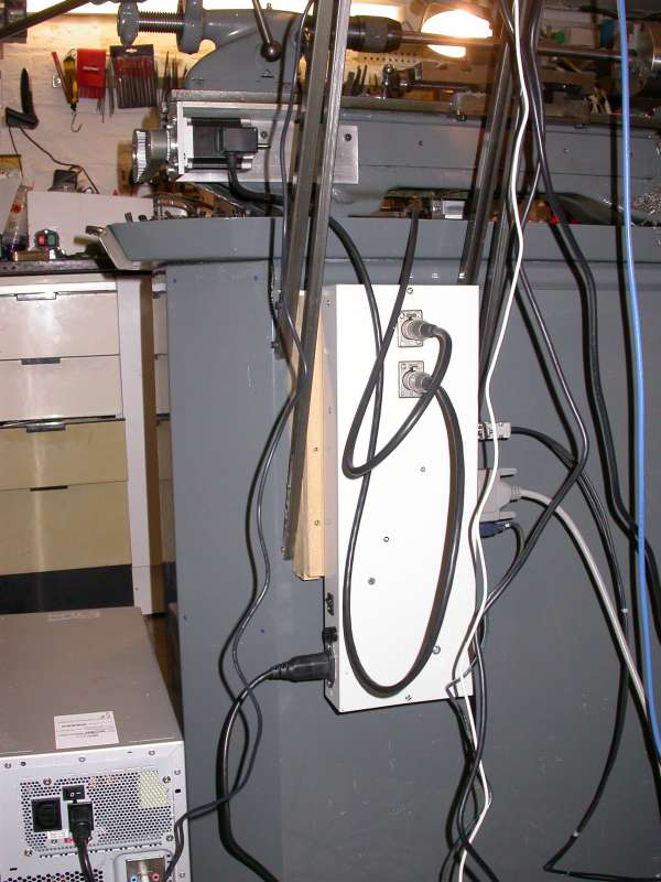
Photo 10: Control box mounted on the back of the lathe stand
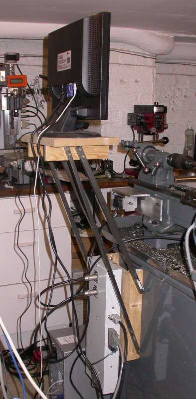
Photo 11: Wood and steel fabricated stand for the LCD screen
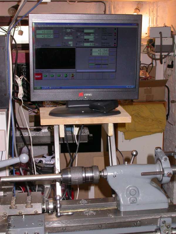
Photo 12: LCD showing a Mach 3 screen
The wooden bracket at the back of the cabinet is just the right width that the finished drive box can be mounted on the MDF plate with a couple of wood screws through holes in the base of the box. This keeps all of the wiring and extraneous hardware neatly out of sight at the back of the machine, while still leaving the on-off switch reasonably accessible.
Plugging it all together
Having mounted the drive box, the D9 plug with the signal cables from the spindle sensor and the E-Stop contacts is pushed into the D9 socket on the drive box, and a parallel port cable is connected from the printer port on the PC to the D25 socket on the driver box.
The motors will also need to be wired up appropriately to their 4-pin XLR plugs; for this, I used 4-core screened cable, connecting the screen at the plug end only, and using the four cores to connect to the two motor coils. If the motors you use are as specified in the parts list, then these are 8-wire motors, and they should be connected in "bipolar parallel" configuration. Unfortunately, the colour coding of stepper motor wires is not standardised, so the Arc and Astrosyn colour coding is different. The connections for the motors is shown in the table below:
Making up the motor cables involves connecting an XLR plug at one end of a suitable length of 4-core screened cable, shortening the wires on the motors to about 3 inches, and connecting the 4-core cable to the pairs of motor wires as specified in the table. A neat way to do this is to use a small plastic "potting box" as a junction box to hide all the joins; drill a hole in the back of the box to allow the box to be stuck in place on the body of the motor with Araldite, with the motor wires coming through the hole. A second hole in the side of the box accepts a rubber grommet, through which you feed the other end of the screened cable. Each solder joint is then sleeved with heat shrink tubing or insulating tape to insulate it from its neighbours, and the lid covers up the mess inside.
Next steps...
That completes the construction of the electronics required for the system. The next step is to add a PC to the system, load Mach 3, configure Mach 3 appropriately to drive the hardware that I have described so far, and start cutting parts. I will describe these remaining steps in part 4 of this 3-part series! If you don't fancy getting embroiled in the murky depths of Mach 3 installation and configuration, it is possible to buy pre-configured Mach 3 systems - called "MACH-in-a-box" - from Lester Caine's Model Engineers Digital Workshop. This is a boxed PC system, with Mach 3 pre-loaded and configured, ready to run.
For those that wish to do their own Mach 3 installation, and wish to do some preparatory work on the PC and software end of things ahead of Part 4, I would recommend taking a look at the documentation on the Mach Support website. The best starting point is a document called "Using Mach 3 turn" which can be found at http://www.machsupport.com/docs/Mach3Turn_1.84.pdf. In particular, this contains sections on installation and configuration of the software; it is important to be familiar with what this document has to say before attempting to load Mach 3 onto a PC. If you get as far as loading Mach 3 and want to give it a whirl, email me at tony @ jeffree.co.uk and I will send you a copy of the Mach 3 XML file that I am currently using on my lathe (this file contains the configuration settings for Mach 3 to work with the hardware as described here). However, more on configuration, XML files and such in the next article.
PARTS LIST
Suppliers and other contact details:
- Arc Eurotrade Ltd, 10 Archdale Street, Syston, Leicester, LE7 1NA, UK. Tel: 0116 269 5693 Website: http://www.arceurotrade.co.uk
- RS Components. Tel: 01536 201201 Website: https://uk.rs-online.com/
- DivisionMaster controllers are no longer available.
- The MACH support website is at http://www.machsupport.com
- The Optoport interface card is supplied by C.R.H. Electronics Design. Website: http://www.diycnc.co.uk/
- Dolphin Partmaster software is available from Dolphin CadCam Ltd., 7 South Dean Road, Kilmarnock, KA3 7RE Tel: 01563 543989 Website: http://www.dolphin-systems.co.uk/
- Maplin's website: http://www.maplin.co.uk/