Introduction
In the first part of this article, I described some improvements to the motor couplings on the Taig/Peatol mill that have dramatically improved the performance of my mill from the point of view of backlash in the drive train, and that form a good basis for a CNC conversion of a manual or a "CNC Ready" Taig mill. This article describes the next step in the process, which involves choosing appropriate stepper motors and building the stepper drive electronics that will offer an appropriate level of performance for a mill of this size.
Size is important
In my article on converting an X3 mill to CNC, I made the observation that my choice of motors/drivers for that project was overkill. Unfortunately, there is a tendency amongst the CNC conversion fraternity to assume that bigger equals better when it comes to the choice of stepper motors. This is not necessarily true, for reasons that are not immediately obvious.
A stepper motor is often characterised by two primary parameters:
- The "holding torque" that the motor can achieve. This is literally the torque that is required to move it away from its current step position while the motor is at rest, and as discussed below, this does not directly indicate how much dynamic torque the motor will usefully generate; and
- The current rating of its coils (often referred to as the motor's "phases" - the stepper motors we are dealing with most often in CNC applications are 2 phase motors - even the ones that have 6 or 8 wires - more on this below).
The naïve assumption would be that more holding torque equals a more powerful motor, equals better performance. However, a more careful analysis can reveal a different story (in much the same way that the torque rating of an IC engine is only a small part of the story - you would be unlikely to take a high torque Diesel and stick it in a racing car - at least, you wouldn't if you wanted to win any races!)
To demonstrate this point, I took three different motors that were to hand, each with very different characteristics, and tested how they performed on my Taig mill following the mechanical changes described in Part 1. The three motors were as follows:
- An original Taig-supplied motor, a "double stack" NEMA-23 frame motor, rated at 200 oz-in holding torque and 1 Amp per phase.
- A similarly sized "double stack" NEMA-23 frame motor, supplied by Arc Eurotrade, product code AC570764525I, rated at 255 oz-in holding torque at 2.5 Amps/phase.
- A rather smaller "single stack" NEMA-23 frame motor, supplied by Astrosyn, part number MY 2801-05, rated at 140 oz-in holding torque at 3 Amps/phase.
I decided to see just how fast each of these motors would drive the Y axis of the mill before running out of steam and losing steps. I used one of my Divisionmaster controllers as the driver, as this allowed me to easily adjust both the stepping rate and the motor current setting as I swapped between motors.
The one apparent disadvantage with using this controller for the test was that the current rating of the Divisionmaster controller is a maximum of 2 Amps/phase; hence, for two of the motors I would be driving them at below their rated current, and, as torque is broadly proportional to motor current, I would therefore effectively be down-rating the maximum torque they could develop by a factor of 4/5 for the Arc Eurotrade motor, and 2/3 for the Astrosyn motor, giving effective holding torque figures of 204 and 93 oz-in respectively. However, as will be seen below, this did not affect the results in the way that you might expect if your expectations were based purely on the motor torque.
- With the original Taig supplied motor, the maximum step rate that could be achieved without the motor losing steps (i.e., the step rate where the motor is only just able to reliably drive the mechanical load) was 1250 half-steps/second; with a 20 TPI leadscrew, and therefore each half-step equating to 1/8th of a thou, this is equivalent to roughly 9.4 inches/minute or 238 mm/minute.
- With the Arc Eurotrade motor, the maximum step rate was 4000 half-steps/second - roughly 30 inches/minute or 762 mm/minute.
- With the smaller Astrosyn motor, the maximum step rate was 7000 half-steps/second - roughly 52.5 inches/minute or 1333 mm/minute.
Torque, torque, torque...
So, what is going on here? Stepper motors generate progressively less torque as the RPM increases, due to a couple of factors:
- Firstly, the inductance of the coils in the motor naturally resists changes in current through the coil; the higher the inductance, the more resistance (known as inductive reactance) there is to any change in current through the coil. So, as stepper motors operate by repeatedly energising their coils with one polarity, and then reversing the polarity, the inductance determines how quickly such reversals can take place. At slow step rates (i.e., low RPM), the time taken for the coil to reach its full current is small relative to the time it spends at full current, so this factor is relatively insignificant; as the step rate increases, the current ramp-up time becomes more and more significant relative to the time at maximum current, to the point where the drive system cannot reach the rated current through the coil before it is time to reverse the drive and start driving the current in the other direction. In other words, the average current through the coil is reduced. This results in a progressive reduction of the torque that the motor can generate as the step rate increases.
- Secondly, the fact that the motor's rotor (which is magnetised) is moving, and therefore, creating a rotating magnetic field, will cause a "back EMF" to be induced in the coils of the motor; this back EMF effectively reduces the voltage that the stepper drives are able to apply across the motor coils. So, as the motor speed increases, it becomes harder and harder for the stepper drives to drive the rated current through the coils; at some step rate, the motor current will be limited by this effect to something less than the rated current, again reducing the torque that the motor can generate.
These two factors result in a speed/torque curve that has a roughly flat region of constant torque at low step rates, and then a region where the torque roughly halves with each doubling of step rate (i.e., this region can be considered as approximating to a constant power region of the curve, as RPM multiplied by torque equals). The absolute maximum step rate is reached when the motor can no longer generate sufficient torque to overcome the mechanical load that it is driving. Figure 1 shows an "idealised" torque versus step rate curve that illustrates this characteristic; it also illustrates another important characteristic of stepper motors, that if you double the drive voltage, you double the step rate that the motor can achieve for a given torque output. Typically, with modern bipolar "chopper" drives, stepper motors can be driven at up to 20 times the nominal voltage that is required to drive the rated current through their coils; this increase in drive voltage consequently has a very beneficial effect in terms of the torque that a motor can generate at higher step rates.
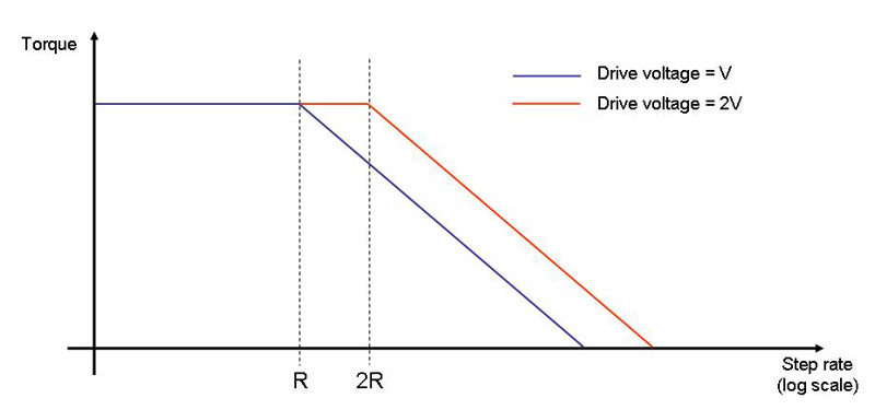
Figure 1: Torque vs Step rate for an "ideal" stepper
So, going back to the three motors under test, what I was seeing was mostly a natural consequence of the different inductances of the motor coils. The Taig 1A/phase motor has the highest inductance; in comparison, the Arc Eurotrade motor, rated at 2.5A/phase for a very similar torque, will have something like 1/3 of the number of turns in its coils (as the magnetic flux generated by a coil, and hence the motor torque, is proportional to Amp-turns) and consequently will have a much lower inductance (as the inductance is proportional to the square of the number of turns). Hence, using the same power supply voltage, the Arc Eurotrade motor can achieve a much higher maximum step rate for the same mechanical load, even though the driver I was using can only at best drive it at 2/5ths of its rated current. At this maximum step rate, the factors mentioned above were in any case limiting the current through the motor to below its current rating, so the fact that the controller could not deliver the rated current was not relevant anyway.
Similarly, with the Astrosyn motor, the torque rating is roughly 0.7 times that of the Taig motor, and the current rating is 3 times that of the Taig, so there will probably be something like ¼ of the number of turns in its windings, and again, a lower winding inductance, and the result from this motor is, not surprisingly, the best performance of the three motors in terms of maximum speed.
The two larger motors will, however, deliver significantly more torque than the smaller motor when running at low speeds with a stepper drive that can deliver the rated current. With a milling machine, you don't need particularly high torque for "rapid" moves when the tool is not actually cutting metal, and when you are cutting metal, you don't need to move the tool particularly quickly, as considerations of cutting rates, tool life and surface finish will require you to move the mill table much more slowly. Consequently, this characteristic of stepper motors, that they deliver the most torque at low speeds, is pretty much ideal for use in CNC milling machines. The decision that you need to take is exactly how much torque is required to operate the mill, given your particular requirements for torque at low speeds and speed/acceleration during rapid moves; from that you stand a good chance of ending up with a drive system that will deliver the required performance without wasting money on motors and power supplies that are too large.
How much torque is enough?
There are a number of factors that come into play here (and this list is not exhaustive!):
- What kinds of material do you expect to be cutting?
- What kinds of cutting feed rates do you need?
- What kind of rapid feed rates do you need?
- How fast do you need the system to accelerate from rest to these speeds?
- How much force do you need at the tool tip, at that feed rate and in that material?
- How heavy is the table, plus the weight of clamping and workpiece, that the motor is required to move?
- How heavy is the mill head (or quill, if you are driving that as the Z axis)?
- How much friction is there in the slideways?
- What is the leadscrew diameter and pitch?
- Is the leadscrew a conventional thread or a ballscrew?
To do an exhaustive calculation you would need to calculate the torque required to accelerate the mechanical components (leadscrew, couplings, saddle, table, head, etc.) at the desired rate and to the desired maximum speeds; there are programs that you can download out there on the Internet that will do the calculation for you if you enter data for your particular machine, and will even suggest particular motors that will work. However, it turns out that for this kind of machine, where acceleration rates and rapid moves need not be excessively fast, these numbers tend to be dominated by the torque needed to generate the required force at the tool tip, so as a rule of thumb, if you have enough torque to do that you will probably be OK on the other factors too. In contrast, with a laser cutting machine, where there are no cutting forces at all, the dominant factor would be how fast you need to accelerate the various moving masses.
So, if you are converting a manual mill, a good place to start is to actually measure the torque needed to crank the handle on each axis while taking a worst-case cut. This can be done very simply by attaching a spring balance to the handle and seeing what deflection is required to get the handle to turn; multiply that figure by how far out from the centre the spring balance is attached, and you have your torque requirement for the motor. Obviously, it is worth increasing this number to add a "safety factor"; however, as seen in the experiments I have described above, increasing the size of the motor too much comes with two kinds of penalty - the top speed that you can achieve will be reduced, and you may end up paying more for your motors (and drivers, and power supply) than is strictly necessary. There is a further potential kind of penalty – overdoing the motor torque can have nasty consequences if the machine locks up, perhaps because it is being driven too fast for the cutter/material/depth of cut - something has to give at this point, and you would really prefer it to be the motor stalling rather than the motor ploughing on and damaging something expensive, such as the leadscrews! This isn't just a theoretical warning - there was a comment on one of the CNC email discussion groups recently mentioning a case where this had actually happened, resulting in the ends of the leadscrews twisting off.
When sizing the motors it is also important to understand, as mentioned earlier, that the "holding torque" figure most often quoted in the motor specification is not the same as the dynamic torque that the motor can actually deliver when it is rotating; typically, the peak dynamic torque available in the "constant torque" part of the curve is significantly less than the holding torque - around 60-70%. So, without actually hooking the motor up and testing it on the actual machine, the only way to understand whether a motor is right for the job is to look at the manufacturer's speed vs torque curve for the stepper drive supply voltage you plan to use, and see whether it can deliver the dynamic torque that is needed at the step rates that are required. However, a reasonable rule of thumb would be to take the worst case torque requirement from the "spring balance" measurement described above, add a safety factor, and then double the result to give the desired holding torque figure.
Torque calculations
As I said earlier, the full set of calculations would involve calculation of the torque required to accelerate the various bits of metal, overcome friction, etc. etc. However, you can get a fairly good feel for what proves to be the dominant factor for us, the force that the system can generate at the tool tip, by doing a much simpler calculation.
The Taig mill has a 20 TPI leadscrew that has a conventional vee-form thread. Screw threads are in effect inclined planes that have been wrapped around a rod; you can therefore very readily calculate the mechanical advantage that a leadscrew gives you, by regarding the motor as delivering a force at unit radius from the axis of the leadscrew, and calculating the distance that the force travels (the circumference of that unit circle) for a linear movement of one thread pitch. For a 20 TPI screw, which has a thread pitch of 0.05", the mechanical advantage is (2*Pi)/0.05, or 125.6. So, if I attach a motor capable of delivering 100 oz-in of torque to a 20 TPI leadscrew, the force generated at the tool tip (if the screw is 100% efficient) would be 785 pounds, or 357 kilos.
Conventional threads are of the order of 20-30% efficient, so this comes down to around 70-110 kilos; however, this is still a respectable amount of force to be appearing at the tool tip on a small desk-top milling machine.
Looking at the manufacturers' speed vs. torque curve for a 40 volt supply, the small Astrosyn motor is capable of delivering a peak dynamic torque of around 90-100 oz-in, and starts to drop below this at a step rate of 1500 steps/second. As that step rate equates to a table traverse rate of around half a metre a minute, things look to be in pretty good shape for using this motor to power the mill, as it is unlikely that you would want to be cutting (and therefore needing maximum torque) at slew rates as high as that. As already discovered with the earlier tests, the absolute maximum step rate with this motor for a 24 volt supply was 3500 full steps/second, which equates to 1.3 metres/minute; using a 38-volt supply (which is what I actually used), this top speed could be even faster. Having seen what 1.3 metres/minute looks like on this mill, these speeds are going to be significantly higher than I will need in practice, and certainly from a safety standpoint, I would feel much more comfortable keeping the speeds well below this figure.
So, the upshot of all of the above is that there seemed to be very little reason to use anything larger than a 140 oz-in holding torque motor to drive a mill of this size with leadscrews of this pitch. However, as has been shown in the motor comparisons, it is also important to choose motors that have a low inductance; these are generally also motors with a high current rating. In passing, I understand that Arc are planning to stock a similar motor to the Astrosyn motor that I used, so these should also be suitable for use in this type of conversion.
The stepper drive
These days, there are a good number of high quality stepper drive systems available for what in reality are reasonable prices, and as a result of what seems to be a bit of a boom in the hobby CNC market in the last couple of years, the range of good quality drives is getting better all the time. I am in the middle of writing a rather longer article that will hopefully offer more detail in terms of the choices to be made in stepper drive types and their various characteristics; for the purposes of this project, I will simply jump to the conclusion of that longer article, and say that you are likely to get the most satisfactory results out of bipolar, microstepping, chopper drives. Briefly:
- Bipolar drives use four wire motors (or 6- or 8-wire motors that have been wired for 4-wire use), and tend to be a little more expensive than Unipolar drives (that need 6-wire motors); however, they also tend to perform better than Unipolar motors of similar specification.
- Microstepping drives allow the motor to be driven to intermediate positions between the full- or half-step positions of the motor; as a result, the motor runs much more smoothly, and quieter, than with a full or half-stepping drive, and the microstepping can also help reduce the effects of "mid-band resonance" to which stepper motors are prone. However, although many microstepping drives offer exotic ranges of microsteps per full motor step, there is absolutely no point in going higher than 8 or 10 microsteps, as most of the benefit has been gained at that point, and all you are doing by going to 16, 32,...256 microsteps and beyond is making your PC or pulse generator card work harder outputting step pulses.
- Chopper drives allow you to use a much higher supply voltage than the "nameplate" voltage declared in the motor specification, and therefore reap the benefits described earlier of higher performance at high step rates. For example, my Astrosyn motors have a coil resistance of 0.7 Ohms and a current rating of 3A; a voltage of 2.1V across the coil is therefore all that is needed to drive the rated current through the coil. A chopper drive is capable of sensing the actual current through the motor; when that level is reached, it literally cuts off the supply to the motor, only re-applying it when the current through the coil drops below the rated current. Chopper drives therefore have a means of setting the maximum motor current; this is achieved by means of a potentiometer, a fixed resistor across a pair of terminals, a set of DIP switches, wire links, etc., depending on the type of drive.
For my X3 mill conversion, I used the 80V 7A stepper drives supplied by Arc Eurotrade; these would work perfectly well for this job, but are rather over-specified, because I only need a 3 Amp drive, and with 2.1V motors, the highest supply voltage I could reasonably use would be around 40 Volts (roughly 20 times the nominal motor voltage). Arc also supply a 40V 3A drive which is a much better "fit" for this job - the electrical characteristics are right, and the drives are also physically significantly smaller and cheaper than the 80V drives. Photo 1 shows one of these units; the anodized Aluminium case is roughly 100x38x60mm, with the base plate extending to 115mm long with two slots for mounting screws. The top plate has a set of DIP switches, some to set the motor current, others to set the number of microsteps. Conveniently, the correct switch positions are screen printed on the plate so that you can't go wrong even if you lose the spec sheet. The settings allow up to 64 microsteps, but for the reasons mentioned earlier, there is no point in going beyond 8 microsteps, and this is the setting I have been using on my mill.
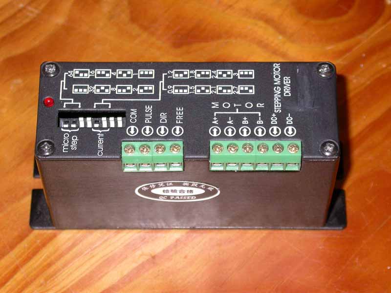
Photo 1: 3A/phase stepper drive unit
The top plate also carries two banks of screw terminals, one for signal connections, the other for the power and motor connections. There is also an indicator LED that lets you know whether power is reaching the drive. I decided that there wasn't much point in having LEDs inside a closed box, so as will be seen later on, I chose to bring these LEDs out onto the side of the box in which I mounted all the drive and power supply components.
Drive system enclosure
Ready-made metal boxes that are large enough to house a set of three stepper drives and their power supply components are hard to come by; one of the most useful boxes I have found to date is supplied by RS, part number 215-5310, the same box I used for the X3 mill drives. This is a long, slim, grey box, 430x150x50mm, and as with the X3 conversion, conveniently attaches to the back of the mill column. Photos 2 and 3 show the base section of the box attached to the column by a couple of M6 screws, screwed into holes drilled and tapped in the steel box-section column of the mill. The box is attached high enough to leave room for adjustment of the bolt through the base of the column that allows the column to be tilted; as a consequence, the box stands rather higher than the top of the box-section column, but will not be as high as the motor mount/stepper motor. As can be seen in Photo 3, I have shifted the Z axis slideways on my mill up a couple of inches to get a bit of extra daylight between the spindle and the table, but even in the "normal" configuration, the top of the box will end up below the top of the stepper motor.
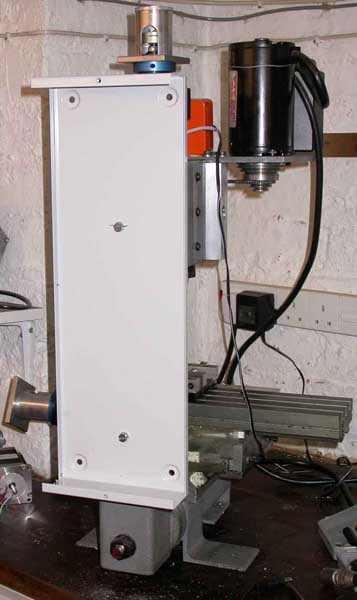
Photo 2: Base of drive enclosure box attached to Z axis column
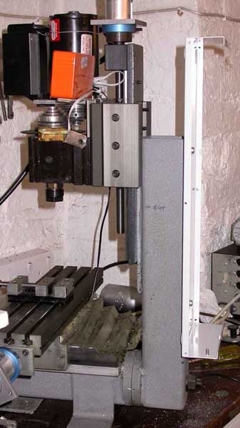
Photo 3: Side view of enclosure attachment
All of the components of the drive system are attached to the "lid" of the box; this has the distinct advantage that the drive electronics can be completely removed from the mill for bench testing if need be. Photo 4 shows the lid in place after all the components have been installed, and gives an idea of the extent of the metalworking that is required:
Photo 4: "Lid" of enclosure in place
- Three holes for the panel mounted 4-pin XLR sockets (RS part number 460-783) that will serve as connections for the cables to the motors. These require circular holes to be punched, 25mm in diameter; I used sheet metal punches for this as I happened to have one the right size. The sockets are held in place with a couple of self-tappers. XLR plugs/sockets are excellent for this application; the pins are good for 15A DC, the plugs are robust, and there is a locking mechanism to prevent inadvertent disconnection of the motors, which can spell death for some drives if this happens with the power turned on.
- Below the XLR sockets are two D-type connectors - one is a 25-way female (RS part number 465-407), the other is a 9-way female (RS part number 544-3749). These sockets are held in place with pairs of locking threaded posts - RS part number 453-886. As with the X3 conversion, the 25-way socket takes the step-and-direction signals to the drivers, and the 4th axis signals are fed back onto the D9 connector as I plan to use one of my Divisionmaster controllers as a 4th axis. If that is not part of your particular plan, the 9-way socket can be omitted. Again, I had a sheet metal punch to hand that is designed for a D9, and I found that by using it twice end-to-end so to speak, it would also do a passable job of roughing out a D25 hole.
- Below the D connectors are the three LEDs that were originally housed in the cases of the three stepper drives.
- Next comes the mains on-off switch - RS part number 249-2906. This is a miniature switch that has a green LED built in; what I did was to wire it to the DC output of the power supply, via a suitable dropper resistor (detail later).
- Next is a standard panel mount IEC mains socket - this takes the kind of mains lead that is commonly used on desktop PCs; RS part number 488-191. This is by no means essential - you could as easily replace this with a mains-cable sized rubber grommet and wire the cable directly into the power supply.
- Right at the bottom is a mains fuse holder - RS part number 311-0009.
- At the top of the side panel you can see two countersunk screw heads - these screws hold one of the stepper drivers in place; the other two drivers are attached to the other long side of the lid of the box, as can be seen in Photo 5. I used some silicon grease under the mounting plates of the drivers to give good thermal conduction to the case. However, if you plan to take the drive LEDs out to the side panel as I did, you will need to delay fitting the drives to the case lid until after making the mods described under "Drive LEDs" below.
Photo 5: View of PSU and drive components attached to lid of enclosure
- Just below the drivers, the power supply smoothing capacitor - RS part number 255-0232 is attached to the side of the lid by means of a plastic bracket - RS part number 203-5698. Unfortunately these brackets only come in bags of 5.
- The large black object at the bottom is the mains transformer - RS part number 223-8178; this is held in place with a single through bolt.
- The final component is the bridge rectifier - I used one that I had to hand, but RS part number 227-8665 would suffice. This is a 25A part, which is way more than necessary; however, there isn't much, if any, price difference between this and a lower specified part, and the 25A part will run cooler. As with mounting the stepper drives, I used some silicon grease under the rectifier to give good thermal conduction to the case.
It is worth getting all of the metalwork and component mounting done before starting to wire the components together.
The power supply
Firstly, a word of warning - the power supply construction inevitably involves wiring up mains voltage components; if you don't consider yourself to be competent (and the word was competent, not confident!) to do this safely, then get it done by someone that is.
All that is needed for a stepper drive power supply is a simple "linear" supply - basically a mains transformer, with the secondary feeding a bridge rectifier, and the DC output is then smoothed by means of a large electrolytic capacitor. The output voltage must not exceed the 40V rated voltage of the stepper drives; hence my choice of a transformer with 25V secondaries that, when wired in parallel, rectified, and smoothed, give a comfortable 38V DC output.
Photo 6 shows the power supply components wired up, and Figure 2 shows the circuit diagram. The resistor, R1, in series with the green mains switch LED, should be chosen such that the current through the LED will be 20 milliamps. With the circuit components as listed, I ended up with a DC output voltage of 38V, which should mean a value of 1.9K Ohms for R1; the most convenient value for R1 was therefore 2K Ohms (I used two 1K resistors in series as this was what I had to hand) - this resistor will dissipate about 0.8 of a Watt, so two ½ Watt resistors in series would be fine for this job.
Photo 6: Power supply components
The terminals on the switch that connect to the LED are conveniently copper coloured as opposed to the silver terminals that switch the mains; I incorporated the resistors in the leads from the switch to the DC output terminals of the bridge rectifier, and covered them in heat shrink sleeving to insulate them. If you decide to use a different transformer, I suggest that you leave the LED connection until after you have had a chance to measure the smoothed DC voltage that your circuit produces; if it is substantially different from the 38V that this circuit produces, the R1 value will need to be changed accordingly.
The rest of the wiring for the power supply is pretty straightforward. Note that the mains earth connects to the earth screw that is welded into one corner of the box lid; there is a matching screw on the base half of the box, and I provided a flying lead terminated in a solder tag that can be fitted to the base earthing point before final assembly.
Note that after fitting the transformer, I insulated the top plate and the end of the mounting bolt (which I also cut as short as possible), as can bee seen in Photo 5. This should not be overlooked - the reason is that there is only just enough room on the box for the thickness of the transformer, and if the metal top plate or bolt were to short to the base of the box, the box plus the mounting bolt would form a single "shorted turn" around the transformer core, which would act as a short across a very low voltage, very high current secondary, and would at the least cause the fuse to blow, but possibly much worse.
Note also that the DC output of the power supply is "floating" - i.e., not connected to the mains earth; this is intentional, as it offers fewer opportunities to construct noisy "earth loops" between the drive system and the PC that will be generating the drive signals.
Once the connections have all been made, power up the power supply to make sure that all is well before continuing with the wiring up of the drives.
Drive LEDs
If you take the top off the stepper drives (a simple plate held by four screws), you can see the red LED at one end - see Photo 7. The LED is conveniently stood off from the PCB so that it is positioned under the hole in the lid; snip the LED leads where they are bent at right angles, and solder a couple of lengths of hook-up wire to the cut ends of the LED leads on the board. I insulated these joints with heat shrink sleeving, but insulating tape would do. Use two different coloured wires and remember which one is soldered to which LED lead - if you get it wrong, the LED won't light, and you may damage either the LED or the drive. Pass the leads through the LED hole in the drive lid and then re-fit the drive lid. The drives can now be fitted to the case lid; it is worth setting the switches for the number of microsteps (I would suggest 8) and the right motor current (3A if you use the Astrosyn motors that I chose, 2.5A if you use the Arc Eurotrade AC570764525I motors) before you fit the drives in the case; you can get to the switches after they are fitted, but it is easier to see what you are doing when they are not fitted to the lid.
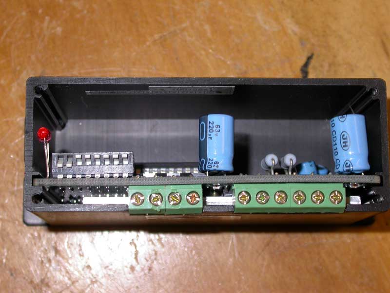
Photo 7: Interior view of a stepper drive unit
The hook-up wires are now cut to length so they will reach the LED holes in the case. Solder the leads of the LED to the wires and insulate the joints. The holes in the case need to be the same diameter as the LEDs - 2mm - and the LEDs can be held in position with a drop of Superglue.
Drive power wiring
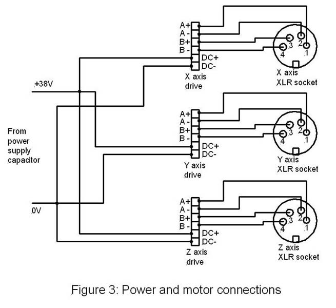
The power supply smoothing capacitor is fitted with screw terminals; these make a very useful connection point for connecting the DC supply to the three stepper drives. The 0V and +38V lines (- and + connections on the capacitor, respectively) should be individually connected from the capacitor terminals to each drive - i.e., use a "star" wiring arrangement rather than "daisy-chaining" the power from drive to drive. I used solder tags on these wires and used reasonably heavy gauge stranded wire for the connections. Keep the wires reasonably short and use cable ties to keep them tidy; these connections can be seen in Photo 5 as the black and red wires running to the drives. The relevant connections on the drives are the terminals marked "DC+" (which is connected to the + terminal of the capacitor) and "DC-" (connected to the - terminal of the capacitor).
Motor socket connections
Use a similar gauge of wire to the one you used for the power connections; ideally, choose four different colours so that you can't get confused about which connection is which, and connect wires to the four motor terminals on one of the drives - the terminals are marked "A+", "A-", "B+", and "B-". Cut these wires to length so that they will conveniently reach one of the XLR sockets, and solder the ends of the wires into the solder buckets on the back of the socket. I have chosen to adopt the same wiring scheme that I used on the Divisionmaster controller for this, so that I can interchange motors between controllers; basically, this scheme connects drive A+ to XLR pin 1, drive A- to XLR pin 2, drive B+ to XLR pin 3 and drive B- to pin XLR 4. It is essential to be consistent in how this wiring is done; get it wrong and you may damage the output stages of the drives by connecting the motor coils the wrong way. Repeat the process for the other two drives.
The power and motor connections are illustrated in Figure 3.
Signal connections
The Arc Eurotrade drives are opto-isolated; unlike the larger drives that I used with the X3 conversion, where a "common" +5V signal was needed, the smaller drives have a "common" connection that must be connected to the 0V (ground) side of whatever system is originating the step and direction signals. On the D25 connector that is used as the parallel port connection on PCs, the 0V connection is available on pins 18 through 25.
The D25 connector carries the "step" and "direction" signals for each of the three main axes, plus the fourth rotary axis, from the PC to the drive system, and the D9 allows the A axis to be connected to an external 4th axis drive, such as my Divisionmaster. I have chosen to adopt what is a fairly common pin connection on the D25 connector so that the drive system will potentially be usable with various different PC-based control software packages, in much the same way as I did for the X3 conversion. The D25 and D9 pin assignments are shown in the following table:
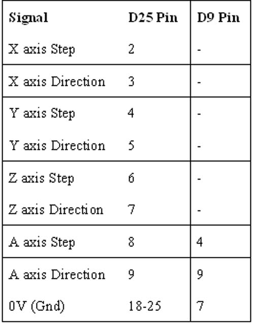
A length of single strand copper wire should be soldered between pins 18 through 25 of the D25 connector; the various 0V connections can then be soldered onto that wire.
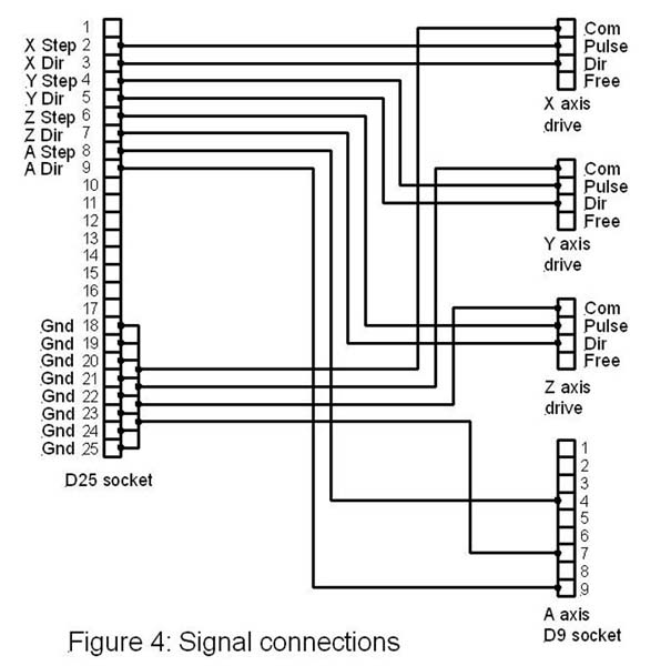
Measure out three lengths of stranded connection wire (again, three different colours is a good plan so that you keep track of which connection is which) long enough to connect between the D25 connector and one of the stepper drives. Use one of the wires to connect the "X axis Step" pin on the D25 to the terminal marked "Pulse" on the stepper drive that will be used to drive the X motor; repeat with the "X axis Direction" pin which is wired into the terminal marked "Dir" on the drive. The third wire connects 0V on the D25 to "Com" (common) on the stepper drive. These three wires should be strapped together with cable ties to keep things tidy. The same process is repeated for the Y and Z axes. At this point, it is worth marking the outside of the box to show which axis (X, Y, or Z) corresponds to which XLR socket and which LED.
The "Free" connection on the stepper drive I left unconnected; it offers the possibility of fitting a switch that removes the drive to the stepper motors (which could be useful if you plan to fit motors with double shafts and handwheels); however, it is just as easy simply to switch off the power to the stepper drives via the mains switch.
The "A" axis signals, pins 8 and 9 of the D25, are connected directly into pins 4 (Step) and 9 (Direction) of the D9 female connector, and 0V on the D25 is wired to pin 7 of the D9.
This arrangement allows the mill to be driven directly from a PC parallel port, using (for example) Mach 3 or Turbo CNC software, both popular and inexpensive "control" software packages. As with the X3 coversion, I have opted to use DeskCNC for this project, but plan to try Mach3 in the future; I have therefore wired the output of the DeskCNC controller board to look like a PC parallel port, making it possible to connect between the DsckCNC board and the stepper drive via a simple "straight through" cable with male D25 plugs at either end, as one would do if driving directly via the PC parallel port.
The signal wiring is illustrated in Figure 4.
DeskCNC board
I bought one of the "second generation" DeskCNC controller boards for this project - the one I used with the X3 conversion was a "first generation" controller board. Both operate from a PC serial port - as this is becoming something of a rarity, there is soon going to be a 3rd generation board available that is driven form the PC's USB port.
The second generation board is physically a lot smaller than the first generation board, and has one or two enhancements as well:
- The maximum step rate has increased from 40,000 SPS to a startling 125,000 SPS. As 40,000 SPS was already plenty for this application (at 8 microsteps this would equate to 25 motor revs per second, or 1.25 inches per second), this particular feature is impressive but doesn't make much difference here.
- The board is capable of processing inputs from an encoder, allowing it to be used to control threading in a CNC lathe, for example. Again, an interesting feature but not particularly useful here.
- The "firmware" for the board is downloaded automatically from the PC; hence, if the firmware needs to be upgraded, all that is needed is to download the latest DeskCNC software from the website and download the firmware into the board from the PC. This is useful, as it means that bug fixes can be applied to the board without having to get a new "chip" from DeskCNC, as was the case with the older board.
- Signal connections to and from the board now use 10-pin "headers" on the board and ribbon cables that plug into them. There are three such headers. The first deals with all of the inputs - emergency stop ("E-stop"), home and limit switches, pause and start inputs. The second deals with various auxiliary output signals - for example there is a PWM output that can be used to control spindle motor speed. The third carries the X, Y, Z, and A axis step and direction signals. A separate 5-pin in-line connector gives the inputs for the encoder if this is fitted.
The new board is in some ways an improvement over the old - the ribbon cables help to keep things tidy, but I can't help feeling that actually, all of the manufacturers are missing a trick here, as there is far too much laborious wiring up to be done to install one of these systems. I am waiting for someone to come out with a neat modular plug-together approach that means all we (the user) have to do is add a power supply and some motors and we have a working system. However, in the meantime, its out with the soldering iron I'm afraid!
I mounted the DeskCNC board in a small ABS plastic box - RS part number 838-647 - as can be seen in Photos 8 and 9. It is easy to make cut-outs at either end for the two D-type connectors - a few strokes with a Stanley knife or similar makes short work of this. The board is held in place with Pritt sticky pads between the track side of the PCB and the box. There is a blue LED on the board - as it is necessary to see whether it is flickering or not in order to determine whether it needs to be programmed, I drilled a hole in the box lid so that this LED can be seen in operation.
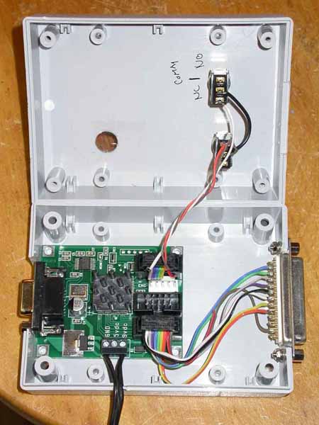
Photo 8: DeskCNC controller wiring
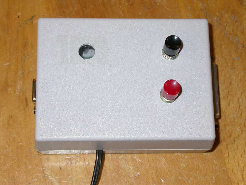
Photo 9: DeskCNC controller box
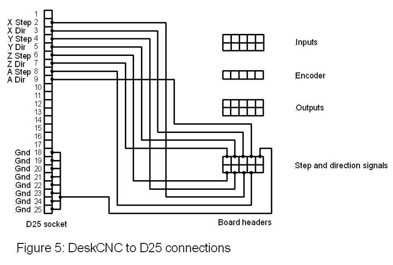
The connections to the D25 female connector all come from the 10-pin header at the bottom right hand side of the board as seen in Photo 8; the connections can be seen in Figure 5.
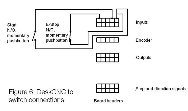
Two further connections to the board are required. The first is to wire the "E-Stop" signal on the "Inputs" header, via a normally closed pushbutton switch, to the 0V or "Gnd" pin. The second is to connect the "Start" pin on the "Inputs" header, via a normally open pushbutton switch to 0V. Pressing the "E-Stop" button (the red button in Photo 9) causes the DeskCNC board to abort any sequences that it is working on and requires active resetting from the PC before the machine will restart. The "Start" button can be used to trigger the "Cycle Start" feature of DeskCNC; it us also used to initiate the process of upgrading the board firmware, so it is a useful switch to have available on the outside of the controller board box. These connections are illustrated in Figure 6.
The final connection to the board is the power supply; the board has its own voltage regulator that generates 5V for the logic circuitry - this requires a 9V unregulated DC input. Alternatively, a regulated 5V supply can be used, bypassing the on-board regulator. I happened to have a spare 9V power supply that was surplus to requirements, so I used that.
Closing comments
That pretty much completes the electronics side of the project. In its current form, the hardware and software seem to perform very much to expectations; the stepper drive operates very much more smoothly and quietly than the old "bi-level chopper" drive, and with smaller motors, still achieving the kind of performance levels appropriate for a machine of this kind. The completed machine can be seen in Photo 10, along with the PC that I have been using to drive it, which is sitting on the old stepper drive box. Actually, the PC itself illustrates one of the advantages of the DeskCNC system; it runs under any version of Windows from Win96 onwards, and this means that you can use "surplus" PCs to run the software, unlike Mach3 that currently needs a reasonably fast machine to run. The laptop I am using is a very old 200 MHz Pentium machine that had long ago become redundant for office use.
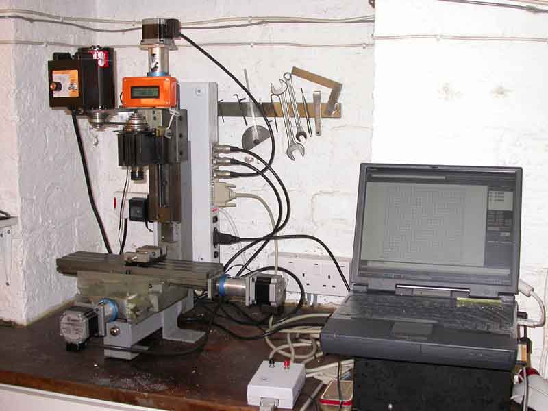
Photo 10: Ready to roll
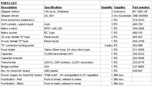
PARTS LIST
Suppliers and other contact details:
1. RS Components. Tel: 01536 201201 Website: http://rswww.com/
2. Model Engineers Digital Workshop is no longer trading.
3. Peatol Machine Tools, Website: http://www.peatol.com
4. Taig Tools, 12419 E. Nightingale Lane, Chandler AZ 85249, USA. Tel: +1 480 895 6978, Website: http://www.taigtools.com
5. Astrosyn International Technology PLC, The Old Courthouse, New Road Avenue, Chatham, Kent, ME4 4QJ, UK. Tel: 01634 815175 Website: http://www.astrosyn.com
6. Arc Eurotrade Ltd, 10 Archdale Street, Syston, Leicester, LE7 1NA, UK. Tel: 0116 269 5693 Website: http://www.arceurotrade.co.uk
7. Mach 2 and Mach 3 can be downloaded from http://www.artofcnc.ca/
8. Turbo CNC can be downloaded from http://www.dakeng.com/turbo.htm
9. DeskCNC software and hardware products can be ordered on-line from http://www.deskcnc.com